Gas furnace pipeline structure and four-section combustion technology

A technology for gas pipelines and gas furnaces, applied in gas fuel burners, burners, combustion methods, etc., can solve problems such as heat loss of gas furnaces, improve heating quality, strengthen heat transfer in furnaces, and have great energy saving potential. Effect

Pending Publication Date: 2021-03-19
HENAN TIANLI THERMOTECHNICAL EQUIP CO LTD
View PDF0 Cites 0 Cited by
  • Summary
  • Abstract
  • Description
  • Claims
  • Application Information

AI Technical Summary

Problems solved by technology

[0004] In view of the above situation, in order to overcome the defects of the existing technology, the present invention provides a gas furnace pipeline structure and four-stage combustion technology to solve the problem of serious heat loss in the existing gas furnace

Method used


Image

  • Gas furnace pipeline structure and four-section combustion technology
  • Gas furnace pipeline structure and four-section combustion technology

Examples


Embodiment 1

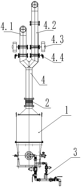
[0017] Embodiment one: by Figure 1 to Figure 2 Given, a gas furnace pipeline structure, including a furnace body 1, the furnace body 1 is connected to an air pipeline 4 and a gas pipeline 3, and the air pipeline 4 includes a first air inlet pipe 4.1 and a second air inlet pipe 4.2 , the first air intake pipe 4.1 and the second air intake pipe 4.2 are respectively provided with a regenerative burner, a reversing valve 4.3 and a hot air butterfly valve 4.4, and the gas pipeline 3 includes a gas inlet 5, a first gas pipeline 7. The second gas pipeline 6 and the gas outlet 8, the gas inlet pipe 5, the first gas pipeline 7 and the second gas pipeline 6 are respectively provided with valves 9, which are independent of each other and can be opened or closed as required. To control the amount of gas entering, a low-fire gas valve 6.1 is set on the second gas pipeline 6, a large-fire gas valve 7.1 is set on the first gas pipeline 7, and two connected regenerative burners are set insid...

Embodiment 2

[0018] Embodiment 2: On the basis of Embodiment 1, the gas inlet 5, the first gas pipeline 7 and the gas outlet 8 are connected to each other in an "L" shape, and the bends are connected by elbows. The first A gas pipeline 7 is grooved at the head and tail for the connection of the second gas pipeline 6, and the connection is welded to form the first gas pipeline 7 and the second gas pipeline 6 to be fed through the gas inlet, and The gas is discharged through the gas outlet, but the pipeline structure is independent of each other. The gas outlet 8 is connected to the furnace body through a joint. The diameter of the second gas pipeline 6 is smaller than the diameter of the first gas pipeline 7. The air The pipeline 4 is a "Y"-shaped tee, and communicates with the pre-furnace body 1 through the bellows 2 .

[0019] In the above embodiment, the second gas pipeline 6 uses a galvanized pipe with a diameter of 4 cm, the first gas pipeline 7 uses a galvanized pipe with a diameter o...


PUM


Abstract

The invention relates to the technical field of gas furnaces, in particular to a gas furnace pipeline structure and a four-section combustion technology. An existing gas furnace is serious in heat loss. The gas furnace pipeline structure comprises a furnace body, the furnace body is connected with an air pipeline and a gas pipeline, and the air pipeline comprises a first air inlet pipe and a second air inlet pipe. The first air inlet pipe and the second air inlet pipe are separately provided with a regenerative burner, a reversing valve and a hot air butterfly valve, the gas pipeline comprisesa gas inlet, a first gas pipeline, a second gas pipeline and a gas outlet, the second gas pipeline is provided with a soft fire gas valve, and the first gas pipeline is provided with a big fire gas valve. Energy conservation and emission reduction are achieved, and good development prospects are realized in the technical field of gas furnaces.

Description

technical field [0001] The invention relates to the technical field of gas furnaces, in particular to a gas furnace pipeline structure and four-stage combustion technology. Background technique [0002] The gas furnace is suitable for normalizing and homogeneous quenching of various metal parts and materials, and uses fuel combustion or other heat sources to generate heat. [0003] Existing gas furnaces generally suffer from serious heat loss and cannot make full use of fuel heat, and the existing gas furnaces have no differential heating method, resulting in the consumption of more fuel when a large amount of heat is not needed. Therefore, new equipment is developed To strengthen the heat transfer in the furnace, change the original low-speed mode, adopt high-speed combustion characteristics to increase the hot gas circulation speed and circulation volume in the furnace, and shorten the uniform temperature time in the furnace to achieve the effect of energy saving. Conten...

Claims


Application Information

Patent Timeline
Patent Type & Authority Applications(China)
IPC IPC(8): F23D14/22F23D14/66
CPCF23D14/22F23D14/66Y02E20/34
Inventor 李明科贾红梅王卫臣王振永杨利伟杨战胜
Owner HENAN TIANLI THERMOTECHNICAL EQUIP CO LTD
Why Eureka
Try Eureka