Non-full pipe electromagnetic flowmeter

An electromagnetic flowmeter and non-full pipe technology, which is applied in the application of electromagnetic flowmeter to detect fluid flow, volume/mass flow generated by electromagnetic effects, liquid/fluid solid measurement, etc., can solve the problem of low applicability and accurate electromagnetic flowmeter In order to achieve the effect of strong applicability, convenient and fast flow measurement, and convenient data recording

Pending Publication Date: 2021-03-16
开封开流仪表有限公司
View PDF0 Cites 0 Cited by
  • Summary
  • Abstract
  • Description
  • Claims
  • Application Information

AI Technical Summary

Problems solved by technology

[0004] Most of the current electromagnetic flowmeters are designed as part-filled electromagnetic flowmeters of a certain size according to the specific channel width, which has low applicability, and it is necessary to customize open channel electromagnetic flowmeters of specific sizes according to different open channel widths; and, the existing The electromagnetic flowmeter has low accuracy and poor applicability

Method used


Image

  • Non-full pipe electromagnetic flowmeter
  • Non-full pipe electromagnetic flowmeter
  • Non-full pipe electromagnetic flowmeter

Examples


Embodiment Construction

[0033] The technical solutions in the embodiments of the present invention will be clearly and completely described below with reference to the accompanying drawings in the embodiments of the present invention. Obviously, the described embodiments are only a part of the embodiments of the present invention, but not all of the embodiments. Based on the embodiments of the present invention, all other embodiments obtained by those of ordinary skill in the art without creative efforts shall fall within the protection scope of the present invention.

[0034] In the description of the present invention, it should be understood that the terms "upper", "lower", "front", "rear", "left", "right", "top", "bottom", "inside", " The orientation or positional relationship indicated by "outside" is based on the orientation or positional relationship shown in the accompanying drawings, and is only for the convenience of describing the present invention and simplifying the description, rather th...


PUM


Abstract

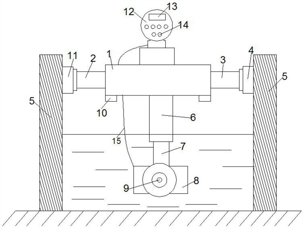
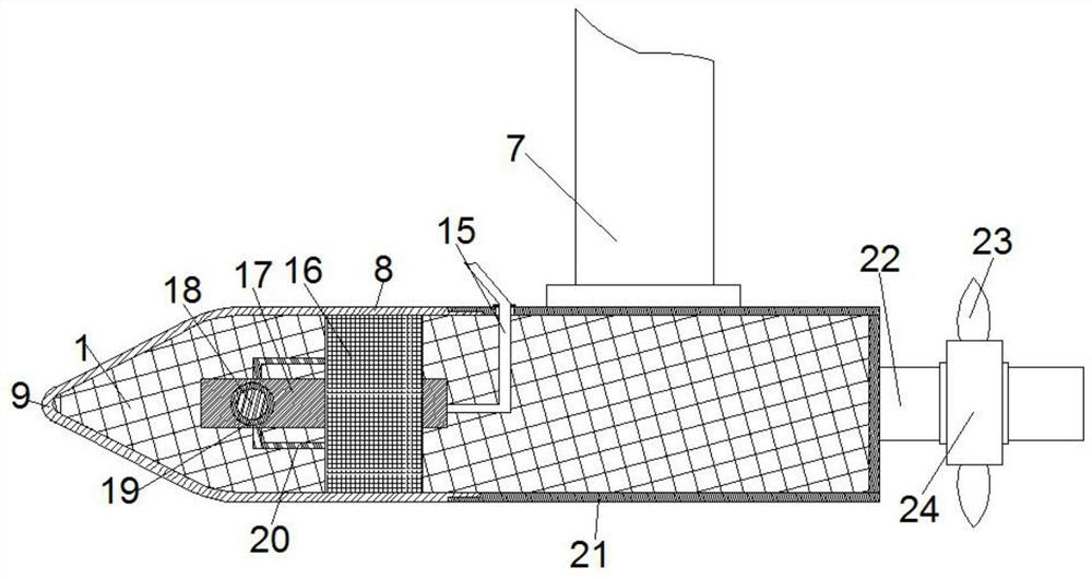
The invention provides a non-full pipe electromagnetic flowmeter, which is erected at each of a first fixed end and a second fixed end of the inner wall of an open channel. The non-full pipe electromagnetic flowmeter comprises a bidirectional telescopic rod, a second telescopic rod, an external display device, and an electromagnetic flowmeter body. The bidirectional telescopic rod is transverselyarranged at the inner wall of the open channel and is perpendicular to the direction of the water flow, and two ends of the bidirectional telescopic rod are both provided with movable ends; the two ends of the bidirectional telescopic rod are fixedly connected with the first fixed end and the second fixed end respectively. The second telescopic rod is fixed at the lower end of the bidirectional telescopic rod; the external display device is fixedly arranged at the upper end of the bidirectional telescopic rod, a controller and a converter are arranged in the external display device, a displaymodule is embedded in the outer end of the external display device, and the display module is electrically connected with a micro-control module; and the electromagnetic flowmeter body is electricallyconnected with the external display device through a connecting wire, and the electromagnetic flowmeter body is fixedly connected with the movable end of the second telescopic rod. The invention discloses the non-full pipe electromagnetic flowmeter which is a non-full-tube electromagnetic flow meter and is high in applicability, high in measurement accuracy degree and wide in application range.

Description

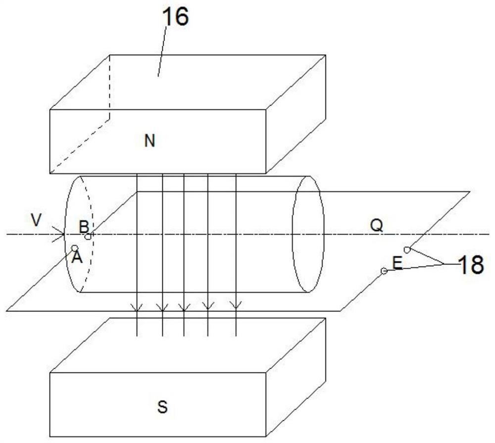
technical field [0001] The invention relates to the technical field of electromagnetic flowmeters, in particular to a non-full-pipe electromagnetic flowmeter. Background technique [0002] Open channel electromagnetic flowmeters are flow meters that measure natural flow on a free surface in a non-full tubular open channel. A waterway that flows in a non-full pipe state is called an open channel, and a non-full pipe electromagnetic flowmeter that measures the flow of water in an open channel is called a non-full pipe electromagnetic flowmeter. [0003] The electromagnetic flowmeter sensor is made by using Faraday's law of electromagnetic induction. When the conductive liquid moves along the measuring tube in the alternating magnetic field perpendicular to the magnetic field line, the conductive liquid cuts the magnetic field line to generate an induced potential, which is perpendicular to the axis of the measuring tube and the magnetic field line. A pair of electrodes are in...

Claims


Application Information

Patent Timeline
IPC IPC(8): G01F1/58G01F23/00
CPCG01F1/58G01F23/00
Inventor 赵志伟王梅马海峰张珂马楠李帅夏石杰田鹏
Owner 开封开流仪表有限公司
Why Eureka
Try Eureka