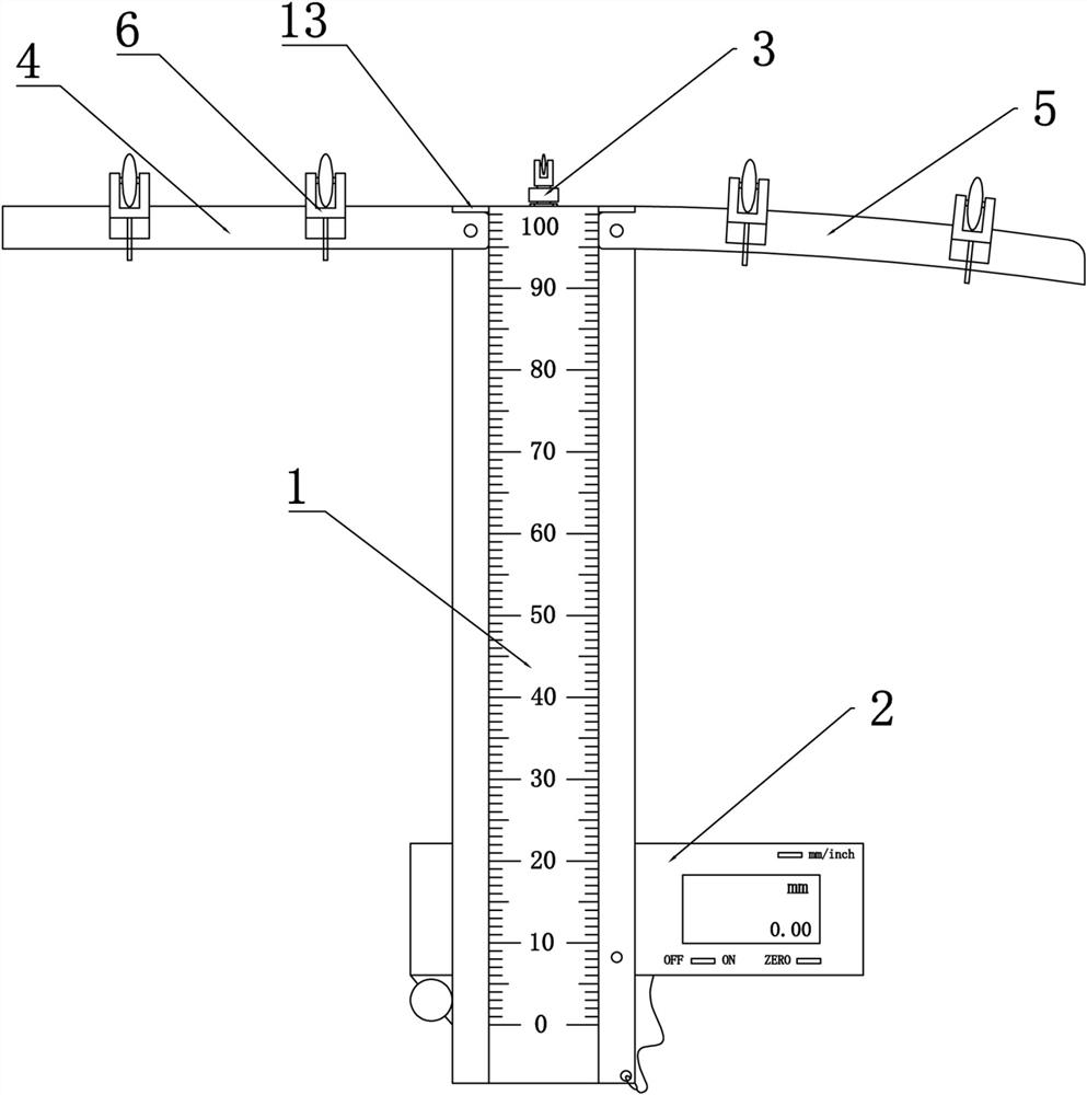
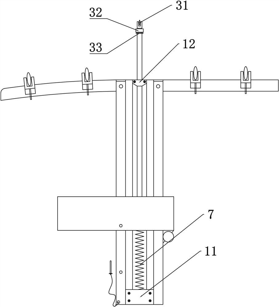
Device for high-precision measurement of slab staggering in and between lining segment rings
A high-precision technology for lining segments, which is applied to measuring devices, mechanical measuring devices, and mechanical devices, etc., can solve the problems of large measurement errors, inability to position correctly, and low accuracy of segment misalignment, and achieve high precision and measurement accuracy. Effortless process, accurate measurement of environmental effects
- Summary
- Abstract
- Description
- Claims
- Application Information
AI Technical Summary
Problems solved by technology
Method used
Image
Examples
Embodiment 1
[0043] Embodiment 1: In the process of tunnel engineering construction, the application of shield construction technology is more and more extensive. During shield tunnel construction, the tunnel wall needs to be reinforced with prefabricated concrete segments. The diameter of the tunnel is usually about 100 meters, and a large number of lining ring segments are required to be assembled to form the tunnel wall. Due to factors such as small-radius curved section construction and shield machine posture correction, segment misalignment will inevitably occur. It is necessary to measure the error between assembled segments in order to judge whether the segment assembly error is within the specified range.
[0044] Most of the existing measurement methods for segment misalignment use general steel rulers, square rulers or vernier rulers for measurement. Due to the segment structure, the visual perception of misalignment is relatively large, and it is difficult for staff to measure C...
Embodiment 2
[0054] Embodiment 2: During the measurement process, the inventor found that after the base guide wheel 6 was installed on the linear base 4 and the arc base 5, the contact surface was reduced. The device of platform is easy to topple over when keeping vertical upright, therefore, further install two groups such as Figure 5 In the double-row wheel structure shown, two sets of double-row wheels provide four fulcrums during use, and use the four fulcrums to contact the segment to form a contact plane, and the measuring device is vertically erected.
[0055] When in use, as long as the four fulcrums on the linear base 4 and the arc-shaped base 5 are close to the segment at the same time, the measuring device can be guaranteed to be in a vertical state. During the moving measurement process, the four fulcrums are always in contact with the segment at the same time. The synchronous movement avoids the problem of frequent adjustment and alignment, and can further improve the measur...
Embodiment 3
[0057] Embodiment 3: Long-term use of the measuring device will cause errors due to objective reasons such as wear and tear, and it is necessary to perform fine-tuning and zeroing operations for processing. In order to solve this problem, as Figure 9-10 The shown base guide wheel 6 includes a wheel seat 61, a fine-tuning screw 62 and a guide wheel. The guide wheel is installed through a rotating shaft in the wheel seat 61. The upper top surface of the wheel seat 61 is provided with a through hole, and the fine-tuning screw 62 is installed by a snap spring. The method fine adjustment screw 62 can be independently rotated relative to the wheel base 61 .
[0058] like Figure 7-8 The shown linear base 4 and the bottom of the slot of the arc base 5 are provided with screw holes, the wheel base 61 is matched with the slot, and the wheel base 61 is installed in the slot through the fine-tuning screw 62 and the screw hole at the bottom of the slot. With the rotation of the fine-tun...
PUM
 Abstract
Description
Claims
Application Information
 - R&D Engineer
- R&D Manager
- IP Professional
- Industry Leading Data Capabilities
- Powerful AI technology
- Patent DNA Extraction
Browse by: Latest US Patents, China's latest patents, Technical Efficacy Thesaurus, Application Domain, Technology Topic, Popular Technical Reports.
© 2024 PatSnap. All rights reserved.Legal|Privacy policy|Modern Slavery Act Transparency Statement|Sitemap|About US| Contact US: help@patsnap.com


