Recyclable garbage packaging equipment
A kind of equipment and garbage technology, which is applied in the field of recyclable garbage packaging equipment, can solve the problems of low work efficiency and inability to prevent the smell of garbage from being emitted, and achieve the effect of convenient centralized processing and improved work efficiency
- Summary
- Abstract
- Description
- Claims
- Application Information
AI Technical Summary
Problems solved by technology
Method used
Image
Examples
Embodiment 1
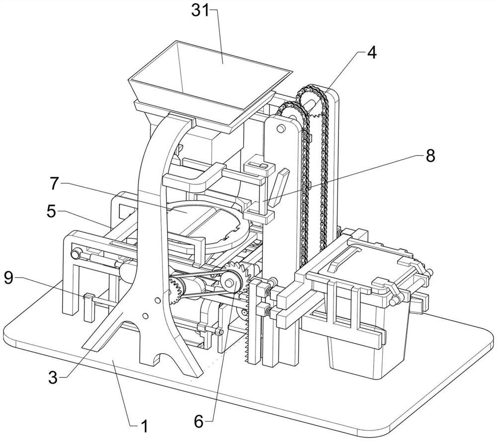
[0100] Such as figure 1 As shown, a recyclable garbage packaging equipment includes a bottom plate 1, a servo motor 2, a support column 3, a blanking frame 31, a transmission mechanism 4, and a sealing mechanism 5. The top right side of the bottom plate 1 is provided with a transmission mechanism 4, and the transmission mechanism A certain part of 4 is provided with a servo motor 2, and the front and rear sides of the top left side of the base plate 1 are symmetrically provided with support columns 3, and a blanking frame 31 is provided between the upper parts of the opposite side of the support column 3, and a blanking frame 31 is provided between the top left side of the base plate 1. There is a sealing mechanism 5.
[0101] When people need to pack recyclable garbage, they push the garbage can with recyclable garbage into the transmission mechanism 4, then manually stretch the plastic bag and put it on the bottom of the blanking frame 31, then turn on the servo motor 2, and...
Embodiment 2
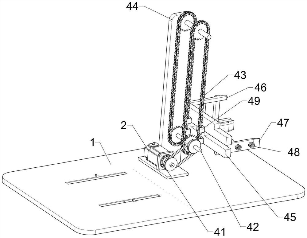
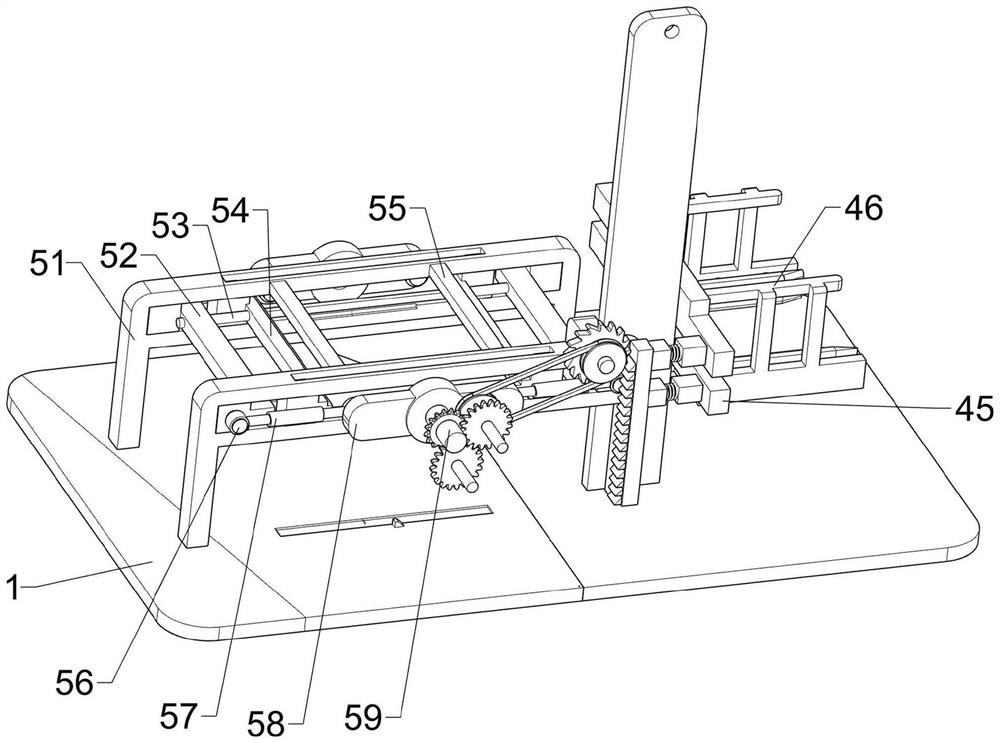
[0103] On the basis of Example 1, such as figure 2 , image 3 , Figure 4 , Figure 5 and Figure 6 As shown, the transmission mechanism 4 includes a first pulley group 41, a first rotating shaft 42, a chain group 43, a support plate 44, a first connecting rod 45, a clamping rod 46, a splint 47, a first spring 48 and a connecting seat 49, and the bottom plate 1 The front and rear sides on the right side of the top are symmetrically provided with a support plate 44, the lower part of the left side of the support plate 44 is connected to the bottom of the servo motor 2, and the upper and lower sides of the opposite side of the support plate 44 are rotatably provided with a first rotating shaft 42 The front and rear sides of the first rotating shaft 42 are provided with a chain group 43, and the first pulley group 41 is arranged between the front part of the first rotating shaft 42 on the lower side and the output shaft of the servo motor 2, and the lower part of the right si...
Embodiment 3
[0110] On the basis of Example 2, such as Figure 7 , Figure 8 and Figure 9 As shown, a limit mechanism 7 is also included, and the limit mechanism 7 includes a second fixed seat 71, a limit disc 72, a movable baffle 73, a second torsion spring 74 and a sixth rotating shaft 75, and the top of the first slide rail 51 The center is provided with the second fixed seat 71, and the second fixed seat 71 is provided with a limit disc 72 between the upper part of the opposite side. The limit disc 72 is located directly below the blanking frame 31. Both sides are provided with the sixth rotating shaft 75, and the sixth rotating shaft 75 is equipped with movable baffle 73 in a rotating manner. The second torsion spring 74 is sleeved on the outside of the sixth rotating shaft 75 on the same side.
[0111] When the rubbish in the dustbin slides down into the plastic bag, then the plastic bag that has packed the rubbish is put on the movable baffle 73, due to gravity, the plastic bag ...
PUM
 Abstract
Description
Claims
Application Information
 - R&D Engineer
- R&D Manager
- IP Professional
- Industry Leading Data Capabilities
- Powerful AI technology
- Patent DNA Extraction
Browse by: Latest US Patents, China's latest patents, Technical Efficacy Thesaurus, Application Domain, Technology Topic, Popular Technical Reports.
© 2024 PatSnap. All rights reserved.Legal|Privacy policy|Modern Slavery Act Transparency Statement|Sitemap|About US| Contact US: help@patsnap.com


