Spherical crystal polishing device capable of automatically adjusting rotating speed

A polishing device and automatic adjustment technology, applied in the direction of grinding/polishing equipment, workpiece feed movement control, spherical grinder, etc., can solve the problems of poor crystal polishing effect, crystal product deviation, high operation requirements, etc., to save time It has the effect of stable clamping and convenient operation with manpower and crystal

Inactive Publication Date: 2021-03-16
宿迁密香凌商贸有限公司
View PDF0 Cites 0 Cited by
  • Summary
  • Abstract
  • Description
  • Claims
  • Application Information

AI Technical Summary

Problems solved by technology

The polishing method of spherical crystal is mainly manual polishing, which has high requirements for the operation of the staff. It needs one hand to press and rotate the spherical crystal to position it to keep it stable, and the other hand holds the polishing block to adjust the crystal. The surface is polished, but with the above polishing method, the artificial positioning is unstable, and the crystal product may be shifted during polishing, resulting in poor polishing effect of the crystal and low polishing efficiency

Method used


Image

  • Spherical crystal polishing device capable of automatically adjusting rotating speed
  • Spherical crystal polishing device capable of automatically adjusting rotating speed
  • Spherical crystal polishing device capable of automatically adjusting rotating speed

Examples


Embodiment Construction

[0016] All features disclosed in this specification, or steps in all methods or processes disclosed, may be combined in any manner, except for mutually exclusive features and / or steps.

[0017] Combine below Figure 1-4 The present invention is described in detail, and for convenience of description, the orientations mentioned below are now stipulated as follows: figure 1 The up, down, left, right, front and back directions of the projection relationship itself are the same.

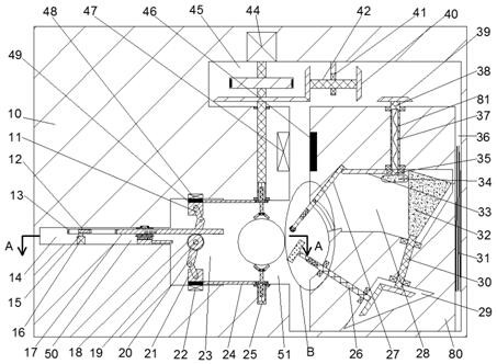
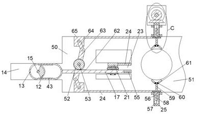
[0018] A spherical crystal polishing device capable of automatically adjusting the rotating speed of the device of the present invention includes a main body 10, a working chamber 51 is arranged in the main body 10, and a polishing chamber 36 is connected to the right side of the working chamber 51. The polishing chamber 36 is provided with a polishing assembly that can automatically adjust the speed of the polishing block according to the surface roughness of the spherical crystal. The left side of the...


PUM


Abstract

The invention discloses a spherical crystal polishing device capable of automatically adjusting the rotating speed. The spherical crystal polishing device comprises a main body, wherein a working cavity is formed in the main body, a polishing cavity is formed in the right side of the working cavity in a communicating mode, a polishing assembly is arranged in the polishing cavity, a first clamp cavity is formed in the left side of the working cavity in a communicating mode, a second clamp cavity is formed in the left side of the first clamp cavity in a communicating mode, and clamp assemblies are arranged in the first clamp cavity and the second clamp cavity. According to the spherical crystal polishing device, a crystal is clamped by clamps on the upper side and the lower side, a clamp motor is started, the crystal is alternately clamped by the clamps on the front side and the rear side and the clamps on the upper side and the lower side, the crystal is driven to rotate and be polishedwhen the crystal is clamped by the clamps on the front side and the rear side, the crystal is driven to reverse when the crystal is clamped by the clamps on the upper side and the lower side so thateach surface of the crystal can be polished, the surface roughness of the crystal is detected through a friction block during polishing, and the more rough the surface is, the higher the rotating speed of a polishing block is.

Description

technical field [0001] The invention relates to the technical field of crystal processing, in particular to a spherical crystal polishing device capable of automatically adjusting the rotating speed. Background technique [0002] Crystal processing needs to go through cutting, embryo pressing, polishing, drilling, engraving, sandblasting and other processes. The polishing method of spherical crystal is mainly manual polishing, which has high requirements for the operation of the staff. One hand needs to press and rotate the spherical crystal to position it to keep it stable, and the other hand holds the polishing block to adjust the crystal. The surface is polished, but using the above polishing method, the artificial positioning is unstable, and the crystal product may be shifted during polishing, resulting in poor polishing effect of the crystal and low polishing efficiency. Contents of the invention [0003] Aiming at the deficiencies of the above-mentioned technologie...

Claims


Application Information

Patent Timeline
IPC IPC(8): B24B11/02B24B41/02B24B41/06B24B49/04
CPCB24B11/02B24B41/02B24B41/067B24B49/04
Inventor 孙开洋
Owner 宿迁密香凌商贸有限公司
Why Eureka
Try Eureka