Power line clamp processing production system

A power line clamp and distance adjustment technology, which is applied in metal processing equipment, manufacturing tools, feeding devices, etc., can solve the problems of high labor intensity in manual work, ejection of power line clamps, and inability to process multiple power line clamps. Improved work efficiency and ease of removal

Inactive Publication Date: 2021-03-16
许子隆
View PDF0 Cites 0 Cited by
  • Summary
  • Abstract
  • Description
  • Claims
  • Application Information

AI Technical Summary

Problems solved by technology

[0003] When processing power line clamps, it is necessary to press and form the power line clamps according to the actual installation position and installation object to bend them into different shapes. However, the following problems often exist in the stamping and forming process of traditional power line clamps: a. During the stamping and forming process of the power line clamp, it is difficult to adjust the bending angle of the power line clamp, so that it is convenient to produce power line clamps of different specifications according to the actual use requirements, and the power line clamps to be bent are often placed one by one manually. The forming process is performed on the device, and it is impossible to process multiple power line clamps at the same time. The manual work is labor intensive, which reduces the work efficiency of the processing work. b. During the traditional power line clamp stamping and forming operations, bending and forming During operation, it is difficult to move and bend both ends of the power line clamp at the same time to avoid deformation of the bending angle of the power line clamp due to excessive force on one side, and the power line clamp cannot be lifted in time after each bending operation is completed. It is convenient for manual removal and improves the working efficiency of molding operations.

Method used


Image

  • Power line clamp processing production system
  • Power line clamp processing production system
  • Power line clamp processing production system

Examples


Embodiment Construction

[0023] In order to make the technical problems, technical solutions and beneficial effects to be solved by the present invention clearer, the present invention will be described in further detail below in conjunction with the accompanying drawings and embodiments. It should be understood that the specific embodiments described here are only used to explain the present invention , and are not intended to limit the present invention.

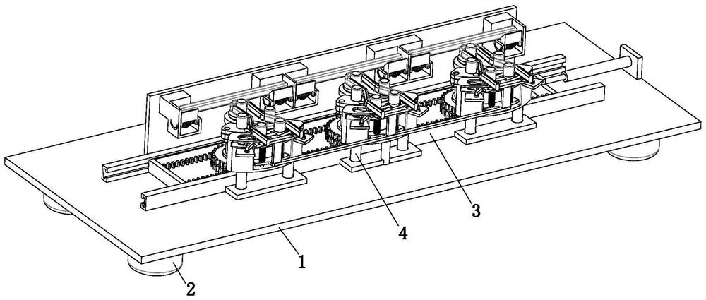
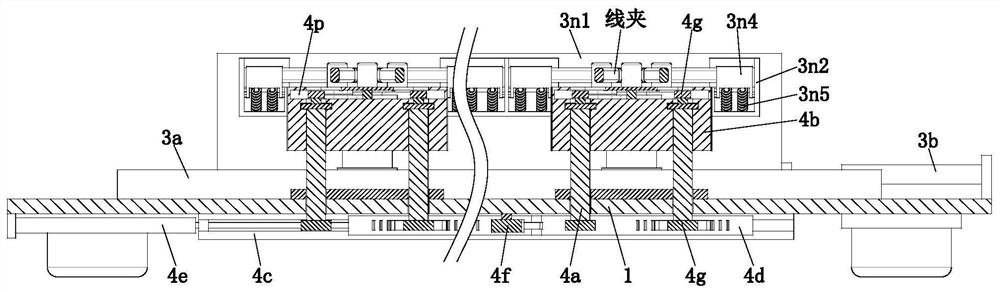
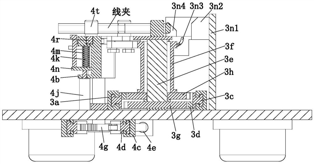
[0024] Referring to 1-7, a power line clamp processing and production system includes an installation base plate 1, a support column 2, a bending mechanism 3 and a distance adjustment mechanism 4, and the lower end of the installation base plate 1 is evenly provided with support columns 2, and the installation base plate A bending mechanism 3 is installed on the upper end of 1, and a distance adjustment mechanism 4 is installed on the installation base plate 1 on one side of the bending mechanism 3 .

[0025]The distance-adjusting mechanism 4 incl...


PUM


Abstract

The invention relates to a power line clamp processing production system. The power line clamp processing production system comprises a mounting bottom plate, supporting columns, a bending mechanism and a distance adjusting mechanism, wherein the supporting columns are uniformly arranged at the lower end of the mounting bottom plate, the bending mechanism is arranged at the upper end of the mounting bottom plate, and the distance adjusting mechanism is arranged on the mounting bottom plate located on one side of the bending mechanism. A plurality of power line clamps to be bent can be placed at the same time through positioning sliding frames arranged at multiple stations, so that the operation efficiency of forming machining operation is improved. Under pushing of the power line clamps, positioning sliding seats begin to rotate downwards through sliding fit between positioning sliding rods and positioning sliding grooves, and receding is conducted for movement of the power line clamps. After the power line clamps completely rotate out of the positioning sliding frames, a bending shaft pushes the power line clamp to rotate to a certain angle, and then the power wire clamps begin tobend under the blocking and limiting action of a distance adjusting sliding rod, so that the required bending effect is achieved.

Description

technical field [0001] The invention relates to the technical field of electric power accessories production, in particular to a power line clip processing production system. Background technique [0002] Wire clamps are iron or aluminum metal accessories that can be fixed on the wires. Most of them need to bear a large pulling force during operation, and some also need to ensure good electrical contact at the same time. [0003] When processing power line clamps, it is necessary to press and form the power line clamps according to the actual installation position and installation object to bend them into different shapes. However, the following problems often exist in the stamping and forming process of traditional power line clamps: a. During the stamping and forming process of the power line clamp, it is difficult to adjust the bending angle of the power line clamp, so that it is convenient to produce power line clamps of different specifications according to the actual u...

Claims


Application Information

Patent Timeline
IPC IPC(8): B21D7/16B21D43/00B21D45/02
CPCB21D7/16B21D43/003B21D45/02
Inventor 许子隆李志
Owner 许子隆
Why Eureka
Try Eureka