Temperature compensation method and device for improving detection precision of ray type thickness gauge
A technology of temperature compensation and detection accuracy, applied in the field of measurement, can solve problems such as excessive deviation of thickness values in cold and hot states, uneven temperature distribution of strip steel, unfavorable strip steel shape quality, etc., to achieve accurate measurement of strip thickness and avoid thickness Calculation and detection, the effect of improving production stability
- Summary
- Abstract
- Description
- Claims
- Application Information
AI Technical Summary
Problems solved by technology
Method used
Image
Examples
specific Embodiment approach 1
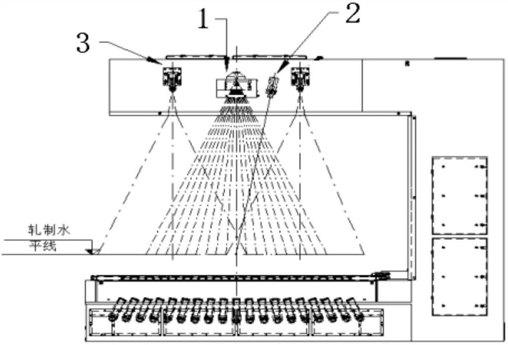
[0025] This specific embodiment provides a temperature compensation method for improving the detection accuracy of a ray-type thickness gauge, including a thickness gauge and a scanning pyrometer 1. The scanning pyrometer 1 is installed on the upper measuring arm of the thickness measuring instrument and is located on the upper arm of the measuring gauge. In the middle position, an air blowing device is installed on one side of the scanning pyrometer 1. The air blowing device is installed at the measurement window of the thickness gauge. The air outlet of the air blowing device faces the scanning pyrometer 1. The pyrometer 1 performs air blowing work; the thickness gauge is installed in the detection area of the thin slab continuous casting and rolling production line, and the temperature compensation process is performed. The temperature compensation process is: the scanning pyrometer 1 scans the strip steel in the detection area It detects and collects the temperature on th...
specific Embodiment approach 2
[0029] This specific embodiment also provides a temperature compensation device applied in specific embodiment 1, including a thickness gauge, a scanning pyrometer 1 and an air blowing device. The thickness gauge has a measurement upper arm and a measurement window, and the scanning pyrometer 1 is installed on the frame of the measuring upper arm, the air blowing device is installed at the measuring window, the middle position of the lower part of the measuring upper arm is provided with an installation opening, the scanning pyrometer 1 is fixed at the installation opening by bolts, and the air outlet of the air blowing device faces the scanning Pyrometer 1.
PUM
 Abstract
Description
Claims
Application Information
 - R&D
- Intellectual Property
- Life Sciences
- Materials
- Tech Scout
- Unparalleled Data Quality
- Higher Quality Content
- 60% Fewer Hallucinations
Browse by: Latest US Patents, China's latest patents, Technical Efficacy Thesaurus, Application Domain, Technology Topic, Popular Technical Reports.
© 2025 PatSnap. All rights reserved.Legal|Privacy policy|Modern Slavery Act Transparency Statement|Sitemap|About US| Contact US: help@patsnap.com

