
Vapor-liquid separator

A vapor-liquid separator and liquid outlet technology, applied in separation methods, dispersed particle separation, chemical instruments and methods, etc., can solve the problems of high vapor resistance, low efficiency, incomplete separation of the separator, etc., and achieve high separation efficiency. , Easy installation and transportation, simple and reliable structure

Pending Publication Date: 2021-03-16
上海贵江机电技术有限公司
View PDF0 Cites 0 Cited by
  • Summary
  • Abstract
  • Description
  • Claims
  • Application Information

AI Technical Summary

Problems solved by technology

[0004] In order to solve the problems of incomplete separation, low efficiency and high vapor resistance of the separator in the prior art, the present invention provides a vapor-liquid separator

Method used


Image

  • Vapor-liquid separator
  • Vapor-liquid separator
  • Vapor-liquid separator

Examples


Embodiment 1

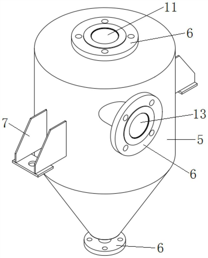
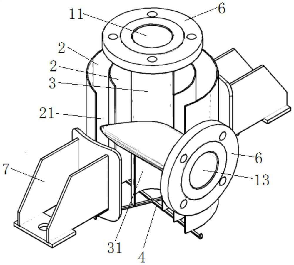
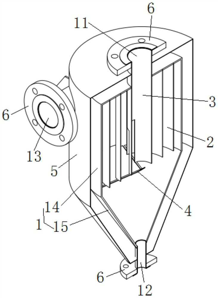
[0023] Such as Figure 1~3 As shown, a gas-liquid separator includes a cylinder body 1, a steam outlet 11 is arranged above the cylinder body 1, a liquid outlet 12 is arranged below the cylinder body 1, and the side of the cylinder body 1 There is a steam inlet 13 on the side, and a plurality of annular deflectors 2 are arranged inside the cylinder body 1, and the plurality of annular deflectors 2 are uniformly arranged in sequence from the inside to the outside, and the adjacent annular deflectors 2 to form an annular guide channel, the annular guide plate 2 is penetrated with a first opening 21 along its axial direction, the steam inlet 13 communicates with the annular guide channel through the first opening 21, and the inlet The steam port 13 is arranged along the tangential direction of the annular deflector 2, the steam inlet 13 is arranged opposite to the first opening 21, and the annular flow guide channel communicates with the liquid outlet 12; the cylinder body 1 is a...


PUM


Abstract

The invention belongs to the technical field of evaporation concentrators, and particularly relates to a vapor-liquid separator which comprises a barrel, a vapor outlet is formed in the upper portionof the barrel, a liquid outlet is formed in the lower portion of the barrel, a vapor inlet is formed in the side portion of the barrel, and a plurality of annular flow guide plates is arranged in thebarrel and sequentially arranged from inside to outside. Annular flow guide channels are formed between the adjacent annular flow guide plates, first openings penetrate through the annular flow guideplates in the axial direction of the annular flow guide plates, the steam inlets communicate with the annular flow guide channels through the first openings, the steam inlets are formed in the tangential direction of the annular flow guide plates, and the annular flow guide channels communicate with the liquid outlet. A flow guide pipe is further arranged in the barrel and located in the annular flow guide plate on the innermost ring, the two ends of the flow guide pipe are communicated with the steam outlet and the liquid outlet respectively, a second opening is formed in the lower end of theflow guide pipe in the axial direction of the flow guide pipe, the second opening is communicated with the annular flow guide channel through the first opening, and the second opening is located below the steam inlet.

Description

technical field [0001] The invention belongs to the technical field of evaporation concentrators, in particular to a vapor-liquid separator. Background technique [0002] During the production process of the evaporative concentrator, when some materials contain sugar and alkaline components, a foam layer with a certain level of liquid level will be produced after heating and flowing. The liquid level in the system evaporator is the uppermost layer. The volume of the foam is large and the weight is light. , It is easy to enter the condensate with the secondary steam, and there are also materials in the foam, which not only causes the loss of product materials, but also causes the impurity of the condensate; such condensate can neither be reused nor discharged directly. [0003] In the existing evaporative concentration system, although there are various separators, as well as drug defoamers, etc., the existing separators include straight cylinder type, partition type, volumet...

Claims


Application Information

Patent Timeline
IPC IPC(8): B01D45/02B01D45/08
CPCB01D45/02B01D45/08
Inventor 任长江
Owner 上海贵江机电技术有限公司
Learn More