
Double-frequency resonance high-isolation two-unit microstrip MIMO antenna

A unit antenna and high isolation technology, applied in the field of wireless communication, can solve problems such as single operating frequency point, high coupling degree of antenna port, complex millimeter wave antenna structure, etc.

Active Publication Date: 2021-03-12
YULIN UNIV
View PDF9 Cites 0 Cited by
  • Summary
  • Abstract
  • Description
  • Claims
  • Application Information

AI Technical Summary

Problems solved by technology

[0004] The purpose of the present invention is to overcome the disadvantages of the above-mentioned prior art, such as complex millimeter-wave antenna structure, single operating frequency point, less selectable far-field radiation characteristics, high coupling between antenna ports, and high commercial cost. The purpose is to provide a dual-frequency resonant high-isolation two-element microstrip MIMO antenna

Method used


Image

  • Double-frequency resonance high-isolation two-unit microstrip MIMO antenna
  • Double-frequency resonance high-isolation two-unit microstrip MIMO antenna
  • Double-frequency resonance high-isolation two-unit microstrip MIMO antenna

Examples


Embodiment 1

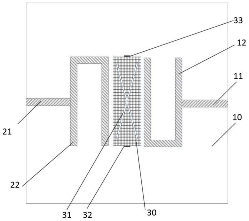
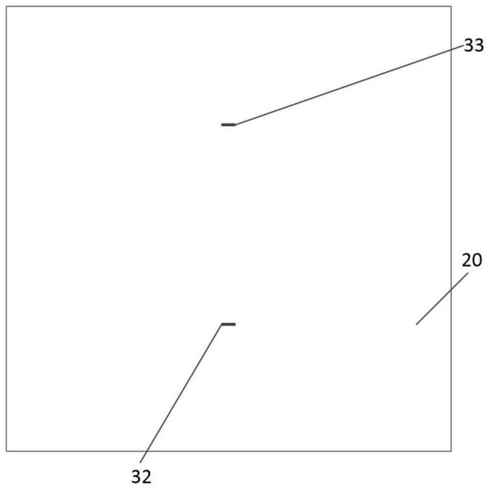
[0036] like figure 1 , figure 2 and image 3 As shown, the first feeding transmission line 11 of the first unit antenna 1 is printed on the right side of the upper surface of the dielectric substrate 10 by using the circuit board printing technology. The length of the first feeding transmission line 11 is 7 ± 2% mm, and the width is 1 mm. ±2% mm, the midpoint of the right edge of the first feeding transmission line 11 coincides with the midpoint of the right edge of the dielectric substrate 10 . Print a type metal patch 12, The lower horizontal side length of the type metal patch 12 is 5 ± 2% mm, the vertical side length is 10 ± 2% mm, and the width of the arm is 1 ± 2% mm. The midpoint of the left edge of the first feeding transmission line 11 and The midpoints of the vertical sides on the right side of the type metal patch 12 coincide. On the right side of the upper surface of the rectangular dielectric substrate 10, the feeding transmission line 11 and Type meta...

Embodiment 2

[0040] Except for the following content, all the other contents are the same as in Example 1.

[0041] The length of the first via hole 32 and the second via hole 33 are both 1.6±2%mm, the width is 0.2±2%mm, and the height is 1.6±2%mm. The first via hole 32 and the second via hole 33 The inside edges are metallized. The first via hole 32 and the second via hole 33 electrically connect the ground plate 20 on the lower surface of the dielectric substrate 10 and the isolation unit 30 on the upper surface.

Embodiment 3

[0043] Except for the following content, all the other contents are the same as in Example 1.

[0044] Along the two diagonal lines on the upper surface of the isolation unit 30, two slender slits 31 are processed, the width of the slit 31 is 0.4 ± 2% mm, and the length is 10 ± 5% mm. The distance between the two slits 31 intersect at the center point of . The distances between the first unit antenna 1 and the isolation unit 30 and between the second unit antenna 2 and the isolation unit 30 are equal to 0.5±2% mm.

[0045] It should be noted that the dielectric substrate used in the embodiment of the present invention is composed of polytetrafluoroethylene FR4, which is commonly used in circuit boards. The relative permittivity of the material is 4.4±2%, and the loss tangent is 0.02±2%. The metal structures of the first unit antenna 1 and the second unit antenna 2 on the left and right sides of the upper surface of the dielectric substrate 10 are the same and have rotational ...


PUM


Abstract

The invention discloses a double-frequency high-isolation two-unit microstrip MIMO antenna, and belongs to the field of wireless communication. According to the present invention, a U-shaped structureis used as the radiation unit of the unit antenna, the two sides of the radiation unit are fed by the microstrip lines to form a first unit antenna and a second unit antenna; the U-shaped metal patchis used as the radiation unit, and the metal patch is added between the U-shaped metal patches of the two unit antennas to serve as the isolation unit, so that the coupling between the unit antennasis reduced. The multi-frequency antenna can work at a plurality of frequency points at the same time, and one multi-frequency antenna can replace a plurality of single-frequency antennas, so that thesize of the wireless communication device is reduced by the multi-frequency antenna, and one of effective ways of miniaturization is realized.

Description

technical field [0001] The invention belongs to the field of wireless communication, and relates to a dual-frequency resonance high-isolation two-unit microstrip MIMO antenna. Background technique [0002] With the occurrence of 5G technology commercial licenses, the world will soon enter the 5G era. Although the fifth-generation mobile communication technology and the fourth-generation mobile communication are only optimized in three aspects: data transmission rate, network capacity and delay. However, 5G mobile communication supports a user experience rate of 0.1-1Gpbs, a connection density of one million per square kilometer, a terminal delay of milliseconds, a traffic density of 10Tbps per square kilometer, a mobile performance of more than 500km / h and 20Gbps peak rate. Compared with the 4G mobile communication system, the above indicators are not minor quantitative changes, but fundamental qualitative changes. In the past, the upgrading of wireless mobile communicati...

Claims


Application Information

Patent Timeline
Patent Type & Authority Applications(China)
IPC IPC(8): H01Q1/38H01Q1/50H01Q1/52H01Q1/48H01Q5/28H01Q5/50H01Q9/04H01Q9/06H01Q13/08
CPCH01Q1/38H01Q1/50H01Q1/521H01Q1/48H01Q9/0407H01Q9/065H01Q13/08H01Q5/28H01Q5/50Y02D30/70
Inventor 崔娟娟吴敏宁王建强刘传星
Owner YULIN UNIV
Learn More