
Dyeing machine convenient to clean

A dyeing machine, a convenient technology, applied in the field of dyeing, can solve the problems of uneven dyeing, low efficiency of exhaust dyeing, unclean cleaning, etc., and achieve the effect of avoiding the precipitation of dye solution, improving the quality of exhaust dyeing, and good dyeing effect

Inactive Publication Date: 2021-03-12
厦门玹珒纺织机械有限公司
View PDF0 Cites 0 Cited by
  • Summary
  • Abstract
  • Description
  • Claims
  • Application Information

AI Technical Summary

Problems solved by technology

[0003] In the process of textile processing, some textile fabrics need to be dip-dyed to make the fabrics have different colors. However, the dip-dyeing efficiency of traditional textile dip-dyeing equipment is low, and it cannot continuously and effectively ensure the uniformity of the dyeing liquid, thereby reducing the fabric’s color. Exhaust dyeing effect reduces the quality of textile products and has certain application limitations;
[0004] Moreover, after the cloth is printed and dyed, a lot of dyeing materials often remain inside the shell. After solidification, it is inconvenient to clean, which not only causes waste of dyeing raw materials, but also requires workers to clean. Washing and cleaning, due to human factors, sometimes the cleaning is not clean. If the cleaning is not clean and thorough, the dyeing will be chaotic and uneven when the cloth is dyed for the second time, which will reduce the quality of the finished product and cannot meet the needs of use.

Method used


Image

  • Dyeing machine convenient to clean
  • Dyeing machine convenient to clean
  • Dyeing machine convenient to clean

Examples


Embodiment Construction

[0030]The following will clearly and completely describe the technical solutions in the embodiments of the present invention with reference to the accompanying drawings in the embodiments of the present invention. Obviously, the described embodiments are only some, not all, embodiments of the present invention.

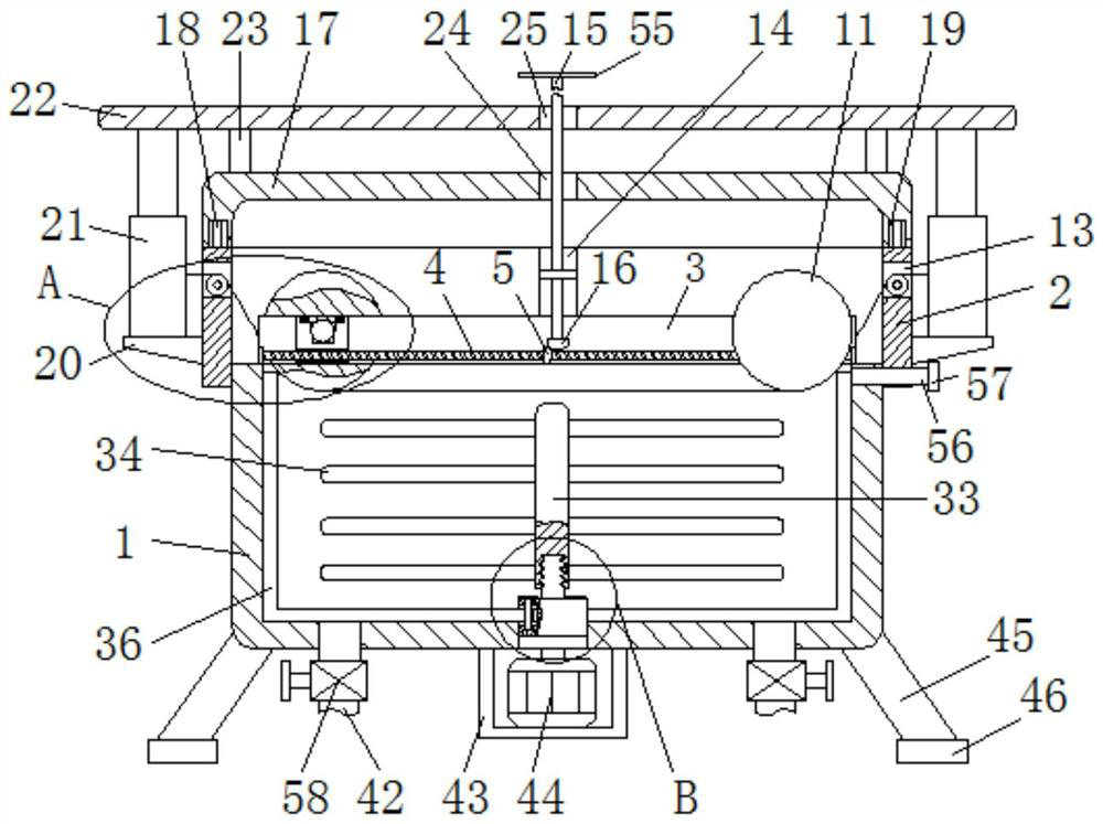
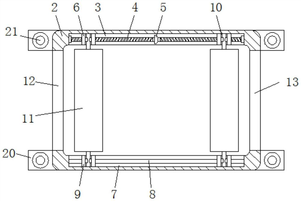
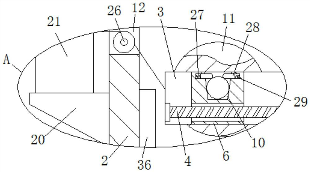
[0031] refer to Figure 1-6 , a dyeing machine that is easy to clean, includes a circular first shell 1 and a square second shell 2, the second shell 2 is fixedly sleeved on the upper part of the first shell 1, the first shell 1 There are two liquid inlet pipes 56 connected symmetrically on the right side. The right end of the liquid inlet pipe 56 runs through the second housing 2, and the mouth of the liquid inlet pipe 56 is plugged with a rubber plug 57. Through the liquid inlet pipe 56, an appropriate amount of dye solution After adding the first housing 1, insert the rubber plug 57 to close the liquid inlet pipe 56. The bottom of the first housing 1 is connected w...


PUM


Abstract

The invention relates to the technical field of dyeing, in particular to a dyeing machine convenient to clean. The dyeing machine comprises a circular first shell and a square second shell, wherein afirst screw rod is rotationally connected to the interior of a first empty groove, two threaded blocks are in threaded connection to the outer side of the first screw rod, a guide rod is fixedly connected to the interior of a second empty groove, two sliding sleeves are slidably sleeved with the outer side of the guide rod, a first roller shaft is placed between two V-shaped grooves in a same longitudinal row, a second bevel gear is fixedly connected with the lower end of the shaft body in a sleeving mode, a first bevel gear engaged with the second bevel gear is fixedly connected with the middle of the first screw rod, and a cover plate is movably connected with the upper end of the second shell. The dyeing device is reasonable in structural design, convenient to use, capable of guaranteeing sufficient dyeing of cloth, convenient to clean, capable of avoiding dye liquor residues, high in practicability and functionality and more convenient to use.

Description

technical field [0001] The invention relates to the technical field of dyeing, in particular to a dyeing machine which is easy to clean. Background technique [0002] The original meaning of textile is taken from the general term of spinning and weaving, but with the continuous development and improvement of the textile knowledge system and scientific system, especially after the production of non-woven textile materials and three-dimensional composite weaving technologies, textile is not only the traditional spinning and weaving Weaving also includes non-woven fabric technology, three-dimensional weaving technology, electrostatic nano-netting technology, etc. Weaving is roughly divided into two processes: spinning and weaving. The most famous textile in China is silk. The development of communication and transportation in China also indirectly affected the commerce and military of the West. [0003] In the process of textile processing, some textile fabrics need to be dip-...

Claims


Application Information

Patent Timeline
Patent Type & Authority Applications(China)
IPC IPC(8): D06B3/10D06B3/34D06B23/04D06B23/20D06B23/30D06B23/02
CPCD06B3/10D06B3/34D06B23/02D06B23/04D06B23/205D06B23/30
Inventor 郭伟伟
Owner 厦门玹珒纺织机械有限公司
Learn More