
Machining method for stepped ring grooves of supercharger sliding bearing

A technology of sliding bearings and processing methods, which is applied in the direction of metal processing equipment, manufacturing tools, milling machine equipment, etc., can solve the problems of affecting processing efficiency, insufficient tool rigidity, large margin of fillet parts, etc. The effect of low cost and small milling allowance

Active Publication Date: 2021-03-12
CHONGQING JIANGJIN SHIPBUILDING IND
View PDF25 Cites 3 Cited by
  • Summary
  • Abstract
  • Description
  • Claims
  • Application Information

AI Technical Summary

Problems solved by technology

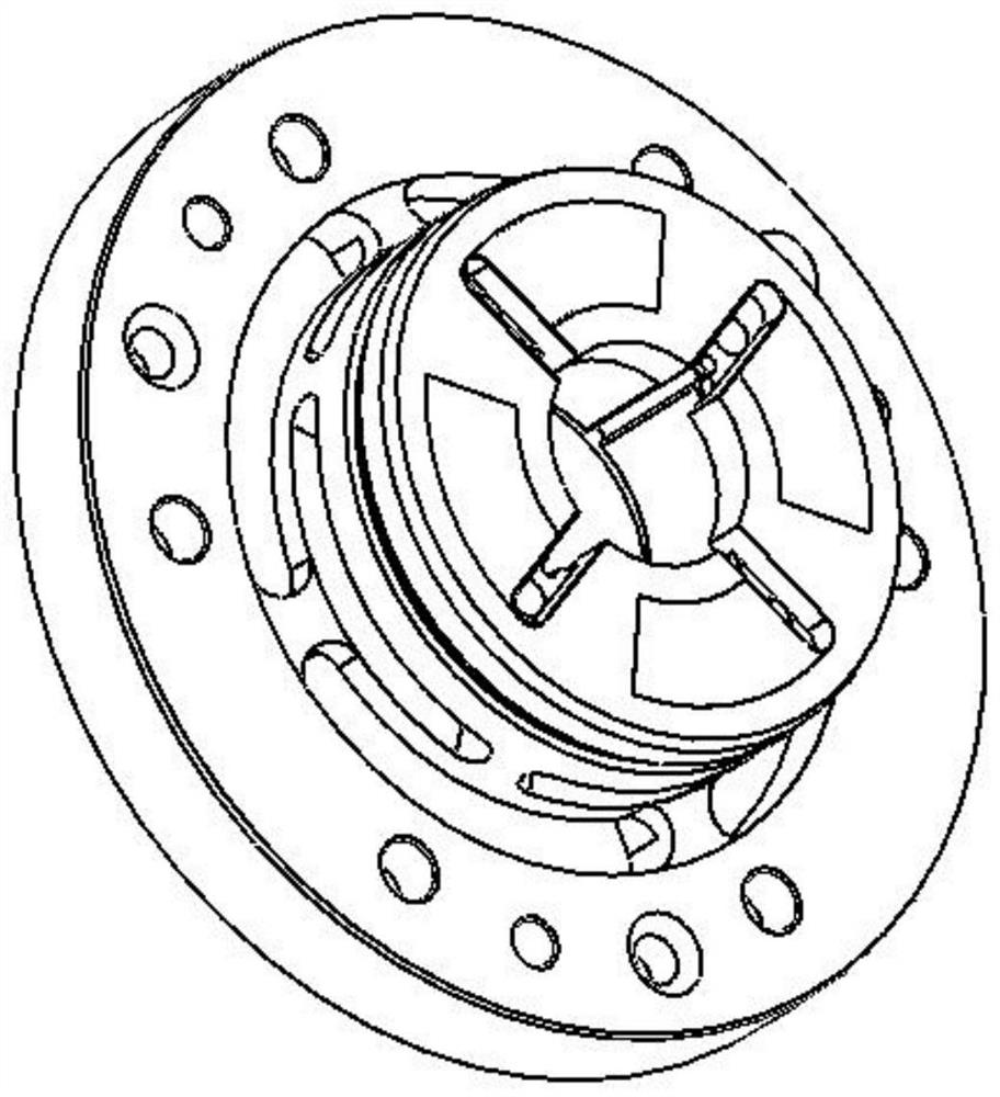
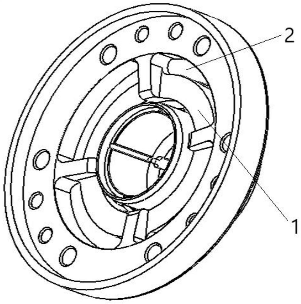
[0002] The supercharger sliding bearing belongs to the bearing precision parts, the structure is as follows Figure 1a - As shown in Figure 2, the material is 15CrNi6, and there are four sets of circumferential stepped ring grooves on the large end surface of the product. The surface of the product needs to be carburized and hardened to improve the surface hardness of the material and obtain better wear resistance; The angle is small, so smaller end mills or keyway milling cutters have to be used in milling. The tool rigidity is insufficient, and the tool breaks frequently, which affects the overall processing efficiency and the processing cost is also high.
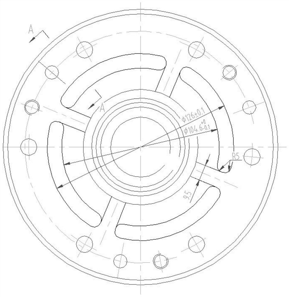
[0003] Processing methods such as image 3 As shown, when D10 is used for root cleaning at the end, the margin of the fillet part is too large, and the tool is easily broken when the root is cleared here. In actual processing, the milling depth is 0.5mm per knife, resulting in extremely low efficiency and wear on the end face of the tool. quick

Method used


Image

  • Machining method for stepped ring grooves of supercharger sliding bearing
  • Machining method for stepped ring grooves of supercharger sliding bearing
  • Machining method for stepped ring grooves of supercharger sliding bearing

Examples


Embodiment Construction

[0024] see Figure 4-Figure 6 , a method for processing stepped ring grooves of supercharger sliding bearings. First of all, in terms of processing methods, this patent application changes the original method of mainly milling, and uses drilling and milling combined processing to remove the remaining corners as much as possible. Quantity, using the combined roughing scheme of D10 and D16 end mills to improve processing efficiency,

[0025] Include the following steps:

[0026] S1. Prepare the supercharger sliding bearing. The supercharger sliding bearing is to be processed with four stepped ring grooves evenly arranged in the circumferential direction. The stepped ring groove is fan-shaped as a whole, including the upper ring groove and communicating with the outer side of the upper ring groove the lower ring groove;

[0027] S2. Drill holes at the center of the circle to be rounded at both ends of each stepped ring groove, and reserve a finishing allowance for subsequent ro...


PUM


Abstract

The invention discloses a machining method for stepped ring grooves of a supercharger sliding bearing. The machining efficiency is higher, and the machining cost is lower. The machining method for thestepped ring grooves of the supercharger sliding bearing comprises the following steps that S1, the supercharger sliding bearing is prepared, the four stepped ring grooves which are evenly arranged in the circumferential direction are to be machined in the supercharger sliding bearing, and the stepped ring grooves are integrally in a fan shape and comprise the upper-layer ring grooves and the lower-layer ring grooves communicating with the outer sides of the upper-layer ring grooves; S2, holes are drilled in the circle centers, to be subjected to fillet machining, of the two ends of each stepped ring groove, and the finish machining allowance of subsequent fillets is reserved; S3, a sinking table is milled at the drilling position of one end of each stepped ring groove to serve as a cutting point of a milling cutter used for subsequent rough machining; and S4, the milling cutters are adopted for conducting rough machining and finish machining on the upper-layer ring grooves and the lower-layer ring grooves correspondingly.

Description

technical field [0001] The invention relates to the technical field of superchargers, in particular to a processing method for a stepped ring groove of a supercharger sliding bearing. Background technique [0002] The supercharger sliding bearing belongs to the bearing precision parts, the structure is as follows Figure 1a - As shown in Figure 2, the material is 15CrNi6, and there are four sets of circumferential stepped ring grooves on the large end surface of the product. The surface of the product needs to be carburized and hardened to improve the surface hardness of the material and obtain better wear resistance; If the angle is small, a smaller end mill or keyway milling cutter has to be used in milling. The tool rigidity is insufficient, and the tool breaks frequently, which affects the overall processing efficiency and the processing cost remains high. [0003] Processing methods such as image 3 As shown, when D10 is used for root cleaning at the end, the margin of...

Claims


Application Information

Patent Timeline
Patent Type & Authority Applications(China)
IPC IPC(8): B23P17/00B23C3/34
CPCB23P17/00B23C3/34B23C2220/605
Inventor 吴琳袁列军邹含青罗攀赵倩
Owner CHONGQING JIANGJIN SHIPBUILDING IND
Learn More