
Calculation method for IGBT junction temperature fluctuation of power electronic converter

A calculation method and power electronics technology, applied in calculation, computer-aided design, complex mathematical operations, etc., can solve problems such as calculation redundancy, inaccurate loss calculation, junction temperature calculation error, etc., to avoid calculation redundancy and improve calculation results Precise, fast calculated effects

Active Publication Date: 2021-03-09
SOUTHWEST JIAOTONG UNIV
View PDF6 Cites 9 Cited by
  • Summary
  • Abstract
  • Description
  • Claims
  • Application Information

AI Technical Summary

Problems solved by technology

[0004] In the currently proposed IGBT junction temperature fluctuation calculation method, the calculation of power loss is mostly equivalent to a half-sine curve, which leads to inaccurate loss calculation and further introduces errors into the calculation of junction temperature; in addition, the current reliable The life model of the performance analysis mainly focuses on the junction temperature fluctuation, and only needs to calculate the maximum and minimum junction temperature values. Therefore, the estimation of the junction temperature at other time points leads to a large amount of calculation redundancy in the iterative calculation, which seriously increases the calculation time of the junction temperature. and the amount of computation

Method used


Image

  • Calculation method for IGBT junction temperature fluctuation of power electronic converter
  • Calculation method for IGBT junction temperature fluctuation of power electronic converter
  • Calculation method for IGBT junction temperature fluctuation of power electronic converter

Examples


Embodiment Construction

[0067] The present invention will be described in further detail below in conjunction with the accompanying drawings and specific embodiments.

[0068] A calculation method for IGBT junction temperature fluctuations of power electronic converters of the present invention comprises the following steps:

[0069] Step 1: Collect the converter-level variables required to calculate the power loss, perform Fourier decomposition on the AC side output current, and obtain the current expression flowing through the IGBT.

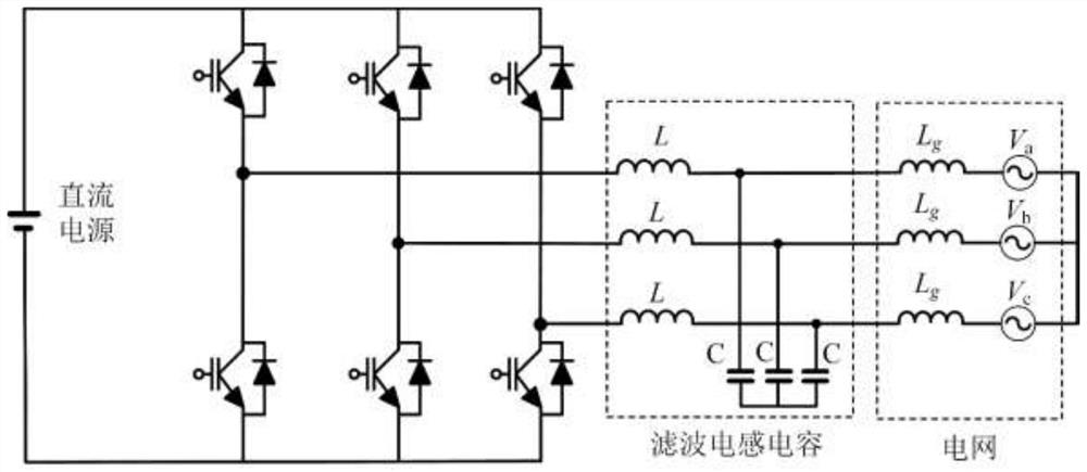
[0070] For the analyzed power electronic converter, take the proportionally reduced three-phase grid-connected inverter as an example, and its equivalent circuit diagram is as follows: figure 1 As shown in the figure, L is the filter inductance value, C is the filter capacitor value, and L g is the equivalent impedance value of the grid, V a , V b , V c is the effective value of the grid equivalent voltage. Due to the symmetry of the IGBT in the converter, one of...


PUM


Abstract

The invention discloses a calculation method for IGBT junction temperature fluctuation of a power electronic converter, and the method specifically comprises the steps of collecting a converter-levelvariable needed by the calculation of power loss, carrying out the Fourier decomposition of an output current at an AC side, and obtaining a current expression flowing through an analyzed IGBT; calculating switching loss and conduction loss corresponding to the alternating current side current peak value respectively, and then obtaining the analyzed power loss of the IGBT in the whole fundamentalwave period; deducing a junction temperature fluctuation expression in a fundamental wave period in combination with a Foster thermal network model, and deriving the junction temperature fluctuation expression to obtain maximum and minimum junction temperature generation time points; and calculating the maximum junction temperature value, the minimum junction temperature value, the junction temperature value at the moment corresponding to the current peak value and the component value of junction temperature fluctuation at the end of the fundamental cycle according to the obtained time points.According to the invention, the IGBT junction temperature fluctuation can be quickly calculated, and the calculation result is accurate, comprehensive and reliable.

Description

technical field [0001] The invention belongs to the field of reliability analysis and state monitoring of power electronic converters, in particular to a calculation method for IGBT junction temperature fluctuations of power electronic converters. Background technique [0002] In the past few decades, although various industries have been striving for higher efficiency and lower cost of power electronic converters, reliability issues have emerged and become more and more important, because power electronic converters One of the main obstacles to reducing energy costs is the large amount of unplanned maintenance on flow converters. At the same time, in order to improve the competitiveness of power electronic converters, how to reduce the design margin while meeting the reliability target has become one of the challenges. As the core component of power electronic converters, IGBT (insulated gate bipolar transistor) is known as the "CPU" of power electronic converters. The deg...

Claims


Application Information

Patent Timeline
IPC IPC(8): G06F30/20G06F17/13G06F17/15G06F111/10G06F119/08
CPCG06F30/20G06F17/13G06F17/15G06F2111/10G06F2119/08
Inventor 葛兴来张艺驰肖秀陈冯晓云苟斌宋文胜
Owner SOUTHWEST JIAOTONG UNIV
Learn More