
Automatic optical cable unwinding and arranging device

An optical cable and automatic technology, applied in the direction of cable/conductor manufacturing, electrical components, and conveying filamentous materials, etc., can solve problems such as low efficiency, broken wires and broken tubes, and defective products, so as to improve work efficiency, facilitate use, and Simple and fast effect

Inactive Publication Date: 2021-03-09
广州大鹏机械设计有限公司
View PDF0 Cites 2 Cited by
  • Summary
  • Abstract
  • Description
  • Claims
  • Application Information

AI Technical Summary

Problems solved by technology

[0002] In the production of twisted optical cables, the twisting method has a high degree of craftsmanship, and the mechanical properties of the optical cable can meet the requirements of use, but defective products will also appear during the production process. come up to recycle
[0003] Now every time there is a need for cable unwinding in the workshop, during the unwinding process, the twisted optical cable needs to be untwisted through the rotating device first, and the optical cable subunit or the end of the optical cable reel to be returned is tied to the reel , and then rotate the reel to wind the optical cable on the reel. After the optical cable sub-unit or the optical cable reel retreats for a short length, the worker will move the support frame bar along the left and right direction to make the optical cable sub-unit or the optical cable reel. The reel is wound and arranged on the reel along the axial direction of the reel, so the efficiency is very low, resulting in a lot of personnel consumption, and it will inevitably lead to a low recovery success rate of the optical cable subunit or the cable reel. The cables are easy to pile up, and the phenomenon of clamping and broken pipes often occurs during the secondary production of cables.

Method used


Image

  • Automatic optical cable unwinding and arranging device
  • Automatic optical cable unwinding and arranging device
  • Automatic optical cable unwinding and arranging device

Examples


Embodiment Construction

[0028] The following will clearly and completely describe the technical solutions in the embodiments of the present invention with reference to the accompanying drawings in the embodiments of the present invention. Obviously, the described embodiments are only some, not all, embodiments of the present invention. Based on the embodiments of the present invention, all other embodiments obtained by persons of ordinary skill in the art without making creative efforts belong to the protection scope of the present invention.

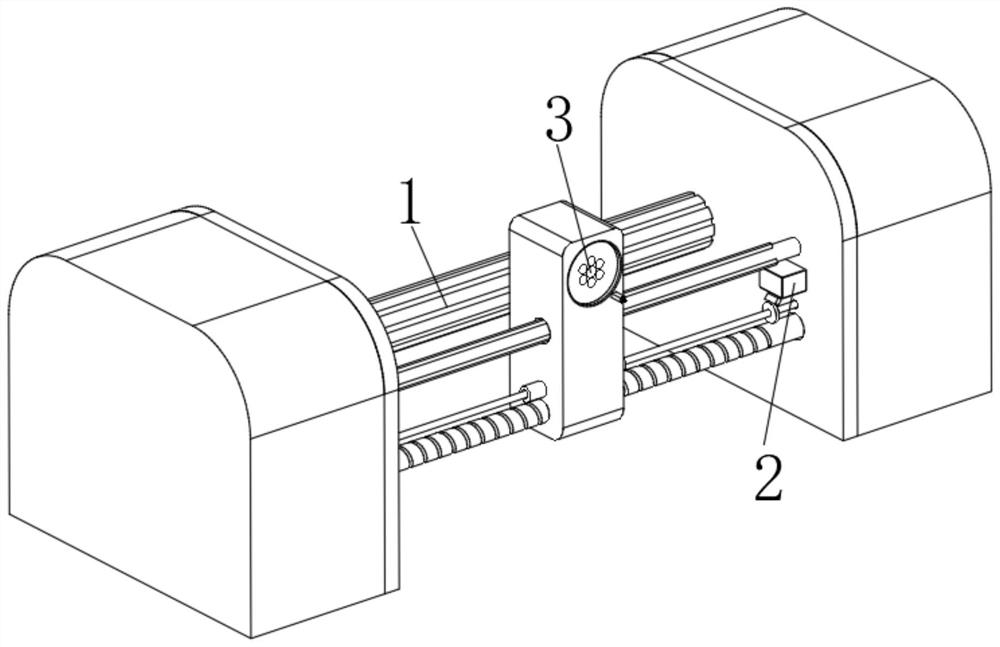
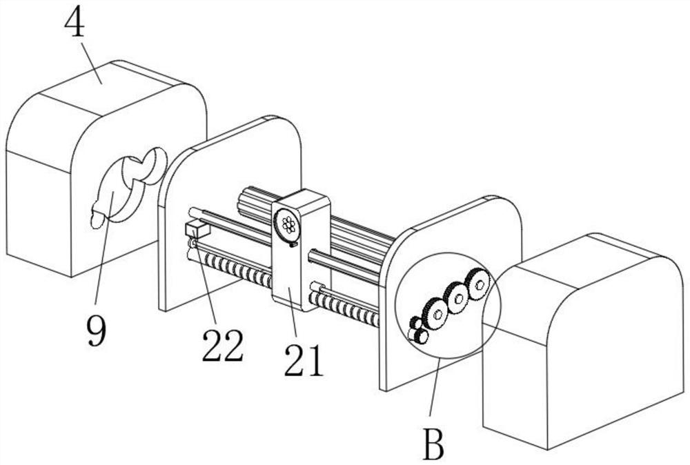
[0029] see Figure 1-11 , the present invention provides a technical solution: an automatic cable unwinding and arranging equipment for optical cables, including: a winding device 1, a direction switching device 2 and an untwisting device 3, and the winding device 1 is used for automatic winding and unwinding of cables When the optical cable is used, the direction switching device 2 is used to arrange the optical cable neatly and orderly on the winding device ...


PUM


Abstract

The invention discloses an automatic optical cable unwinding and arranging device which comprises a winding device, a direction switching device and an untwisting device, the winding device is used for automatically winding optical cables in unwinding, the direction switching device is used for arranging the optical cables on the winding device in order and is in linkage with the winding device, and the untwisting device is used for removing the twisting state of the optical cables, facilitates the subsequent twisting processing, and is in linkage with the direction switching device and the winding device. According to the automatic optical cable unwinding and arranging device, a problem that the conventional optical cable unwinding and arranging equipment is difficult to automatically remove the twisting state of the optical cables and automatically wind the optical cables in order in use is solved, the functions of automatic untwisting and automatic orderly arranging and winding canbe realized by only one driving source, the operation is simple and rapid, the working efficiency is improved, and the device is convenient for people to use.

Description

technical field [0001] The invention relates to the technical field of unwinding and arranging optical cables, in particular to an automatic uncable and arranging equipment for optical cables. Background technique [0002] In the production of twisted optical cables, the twisting method has a high degree of craftsmanship, and the mechanical properties of the optical cable can meet the requirements of use, but defective products will also appear during the production process. Come up and recycle. [0003] Now every time there is a need for cable unwinding in the workshop, during the unwinding process, the twisted optical cable needs to be untwisted through the rotating device first, and the optical cable subunit or the end of the optical cable reel to be returned is tied to the reel , and then rotate the reel to wind the optical cable on the reel. After the optical cable sub-unit or the optical cable reel retreats for a short length, the worker will move the support frame ba...

Claims


Application Information

Patent Timeline
Patent Type & Authority Applications(China)
IPC IPC(8): B65H54/553B65H54/40B65H54/30B65H54/70H01B13/02
CPCB65H54/30B65H54/40B65H54/553B65H54/70B65H2701/341H01B13/0207
Inventor 谢绍良
Owner 广州大鹏机械设计有限公司
Learn More