Cut-off and firewood chopping device for wood
A technology for chopping wood and wood, applied in the field of wood cutting and wood chopping devices, can solve the problems of manual cutting and single function, and achieve the effect of improving work efficiency
- Summary
- Abstract
- Description
- Claims
- Application Information
AI Technical Summary
Problems solved by technology
Method used
Image

Examples
Embodiment 1
[0078] A cutting and chopping device for timber, such as figure 1 As shown, it includes a base 1, a placement mechanism 2 and a firewood splitting mechanism 3, the right side of the base 1 is connected with the placement mechanism 2, and the left side of the base 1 is connected with the wood splitting mechanism 3.
[0079] When needing to split firewood, the wood is placed on the placement mechanism 2 earlier, and then the wood is moved to the left, so that the firewood splitting mechanism 3 splits the wood.
Embodiment 2
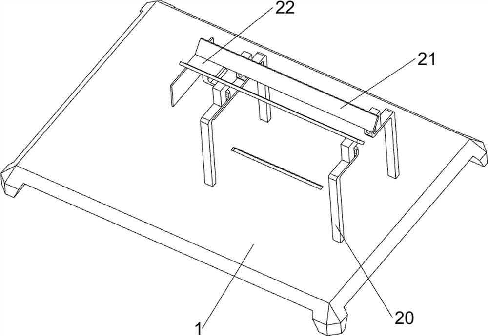
[0081] On the basis of Example 1, such as Figure 2-3 As shown, the placement mechanism 2 includes a first pillar 20, a baffle 21 and a bearing platform 22, the four sides of the right part of the base 1 are connected with the first pillar 20, and the tops of the horizontal first pillars 20 are connected with a baffle 21 , a carrying platform 22 is connected between the left side of the baffle plate 21 .
[0082] When needing to chop wood, the wood is first placed on the carrying platform 22, and then the wood is pushed to move to the left, so that the wood splitting mechanism 3 splits the wood.
[0083] Wood chopping mechanism 3 comprises installation table 30, the first slide block 31, the first tooth bar 32, the second slide block 33 and blade 34, and base 1 left side is connected with installation table 30, and installation table 30 left front and back both sides are all connected There is a blade 34, a second slider 33 is slidably connected to the front and rear sides of...
Embodiment 3
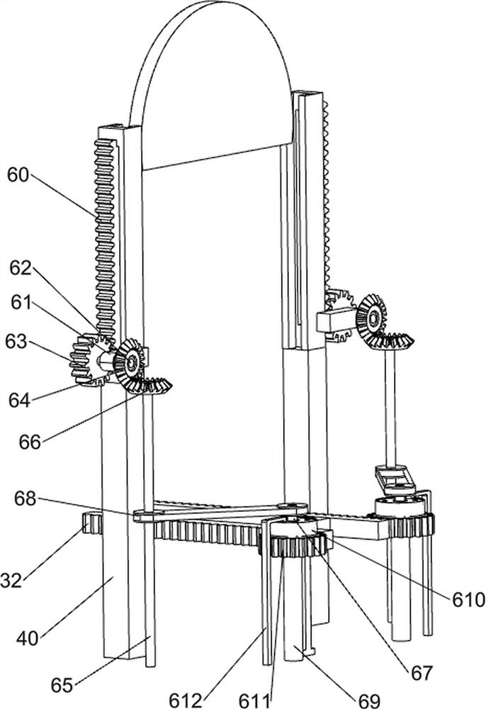
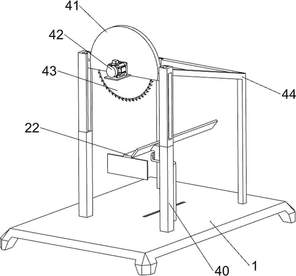
[0086] On the basis of Example 2, such as Figure 4-8 As shown, a cutting mechanism 4 is also included. The cutting mechanism 4 includes a second pillar 40, a third slider 41, a servo motor 42, a sawtooth 43 and a first bracket 44, and the left side of the base 1 is connected with a second A third slider 41 is slidably connected between the pillar 40 and the second pillar 40 , a servo motor 42 is connected to the left side of the third slider 41 , the output shaft of the servo motor 42 is connected with a sawtooth 43 , and the sawtooth 43 is located on the third slider 41 Inside, the right side of the base 1 is connected to the first support 44 , and the left side of the first support 44 is connected to the second support 40 .
[0087] Before chopping wood, the wood needs to be cut off. The wood is first placed on the carrying platform 22, the servo motor 42 is started, the output shaft of the servo motor 42 rotates to drive the sawtooth 43 to rotate continuously, and then the...
PUM
 Abstract
Description
Claims
Application Information
 - R&D
- Intellectual Property
- Life Sciences
- Materials
- Tech Scout
- Unparalleled Data Quality
- Higher Quality Content
- 60% Fewer Hallucinations
Browse by: Latest US Patents, China's latest patents, Technical Efficacy Thesaurus, Application Domain, Technology Topic, Popular Technical Reports.
© 2025 PatSnap. All rights reserved.Legal|Privacy policy|Modern Slavery Act Transparency Statement|Sitemap|About US| Contact US: help@patsnap.com