Rotary table of desktop mechanical arm, desktop mechanical arm and robot

A technology of manipulators and turntables, applied in manipulators, program-controlled manipulators, claw arms, etc., can solve the problems of complex overall structure design, high manufacturing cost, and low safety

Pending Publication Date: 2021-03-09
SHENZHEN YUEJIANG TECH CO LTD
View PDF12 Cites 22 Cited by
  • Summary
  • Abstract
  • Description
  • Claims
  • Application Information

AI Technical Summary

Problems solved by technology

[0003] At present, desktop manipulators are usually educational desktop manipulators. The big arm and forearm face the front side of the turntable, and the objects grasped by the end are light in weight and light in load. The desktop manipulator can run smoothly by its own gravity; However, with the improvement of the industrial level, in order to meet the market demand, the desktop robotic arm is gradually developing towards industrial applications, such as in the fields of visual sorting and assembly line handling, where it is required to grab heavier objects. At this time, the load becomes Large, so that the overall center of gravity is close to its end and away from the base, the base will shake during work and prone to rollover, etc., the safety is low, and it cannot meet the application conditions of industrial grade
In addition, the synchronous pulley deceleration method is adopted in the turntable of the existing desktop manipulator to realize the transmission of the boom and the forearm. For example, a compact belt-driven closed For small four-axis robots, because the primary timing belt is arranged close to the turntable, in order to avoid interference between the primary synchronous belt and the structure on the turntable (such as motor fixing screws, etc.) The convex bracket of the driving pulley limits the position of the primary synchronous belt. There are many auxiliary components and the manufacturing cost is high; and due to the restriction of the convex bracket and other components on the primary synchronous belt, in order to avoid structural interference, a It is difficult to increase the size of the pulley of the first-stage synchronous pulley, resulting in a low reduction ratio and poor deceleration effect, which in turn affects the control accuracy
Further, for example, the Chinese patent application number CN201910571696.6 discloses a small static load balancing belt drive mechanical arm, the first-stage synchronous pulley and the second-stage synchronous pulley of the synchronous pulley deceleration assembly are respectively arranged on the turntable. Space on both sides inside and outside, the overall structure design is complex, disassembly and assembly are difficult, and daily maintenance is inconvenient; another example is a vertical inverted compact small four-axis robot disclosed in a Chinese patent with application number CN201810921858.X. In addition to the situation that the base will shake during work and prone to rollover, the designed upper and lower synchronous pulleys have a large span and unreasonable space layout, making the structure not compact enough

Method used


Image

  • Rotary table of desktop mechanical arm, desktop mechanical arm and robot
  • Rotary table of desktop mechanical arm, desktop mechanical arm and robot
  • Rotary table of desktop mechanical arm, desktop mechanical arm and robot

Examples


Embodiment Construction

[0070] The solutions in the embodiments of the present invention will be clearly and completely described below in conjunction with the accompanying drawings in the embodiments of the present invention. Apparently, the described embodiments are only some of the embodiments of the present invention, not all of them. Based on the embodiments of the present invention, all other embodiments obtained by persons of ordinary skill in the art without creative efforts fall within the protection scope of the present invention.

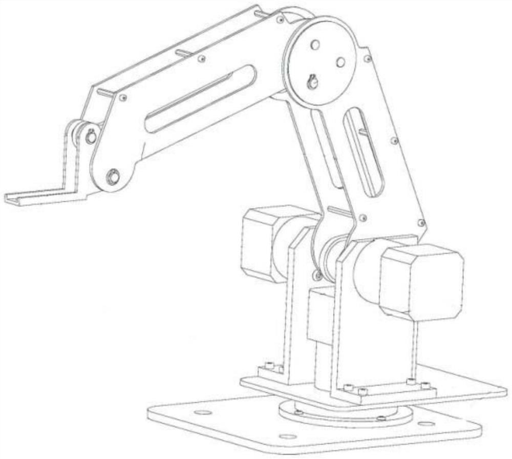
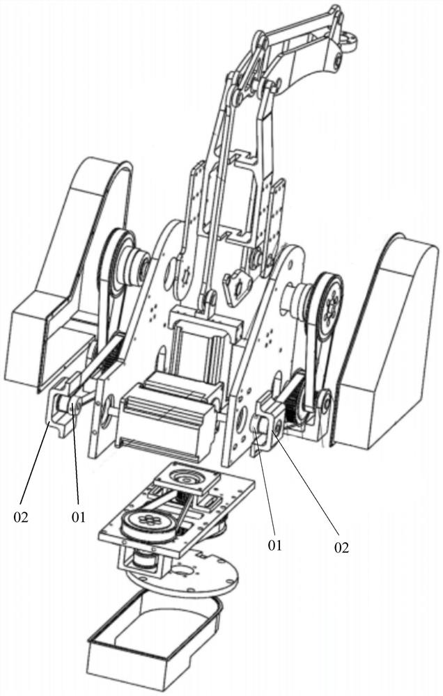
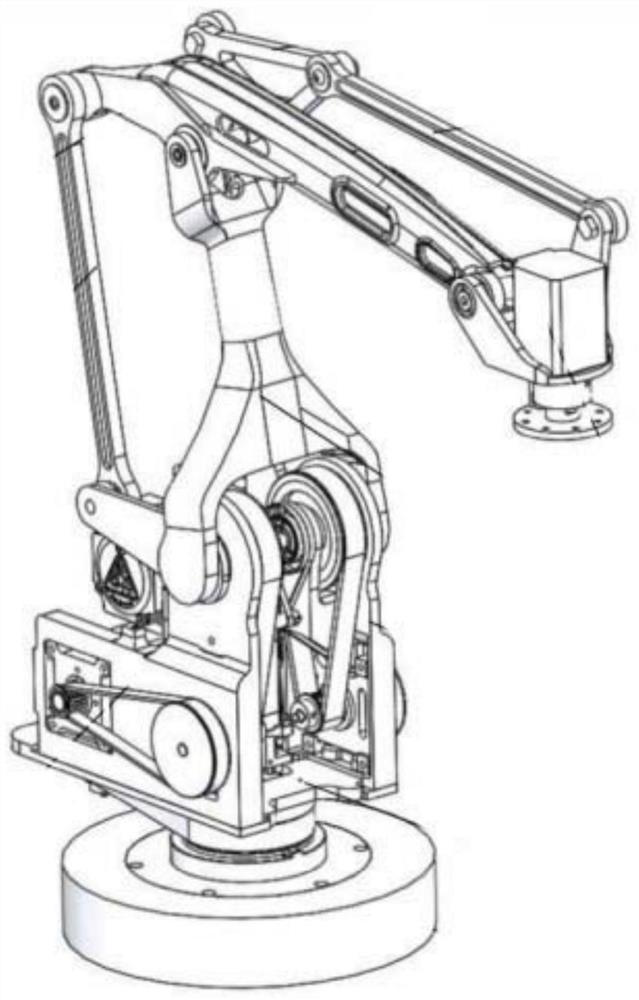
[0071] As a subcategory of robotic arms, the desktop robotic arm consists of a base, a turntable, a large arm, a small arm, a terminal, and a rotary table drive motor, a large arm drive motor, and a small arm drive motor. The rotary table and the base are rotatably connected. They are respectively connected to the turntable and the small arm, the small arm is connected to the end, the end is used to set the actuator, the turntable drive motor is used to drive the...


PUM


Abstract

The invention discloses a rotary table of a desktop mechanical arm. The rotary table is provided with a base, a large arm driving motor, a small arm driving motor, a large arm speed reducing assemblyand a small arm speed reducing assembly, wherein the large arm driving motor and the small arm driving motor are located at the rear side of the base and arranged in an up-down stacking manner; the large arm speed reducing assembly and the small arm speed reducing assembly are located on the left outer side surface and the right outer side surface of the base separately; the large arm speed reducing assembly comprises a large arm first-level synchronous belt wheel and a large arm second-level synchronous belt wheel located between the large arm first-level synchronous belt wheel and the base;and the small arm speed reducing assembly comprises a small arm first-level synchronous belt wheel and a small arm second-level synchronous belt wheel located between the small arm first-level synchronous belt wheel and the base. According to the rotary table of the desktop mechanical arm, the safety is improved; for a speed reducing synchronous belt, arrangement for auxiliary assemblies is reduced, so that the manufacturing cost is reduced, and the speed reducing ratio can be increased and the speed reducing effect can be improved, so that the control precision is ensured; and moreover, the rotary table of the desktop mechanical arm is simple in structure, easy to detach and install, and convenient to maintain.

Description

technical field [0001] The invention relates to the technical field of desktop manipulators, in particular to a turntable of a desktop manipulator, a desktop manipulator and a robot. Background technique [0002] As a subcategory of robotic arms, the desktop robotic arm consists of a base, a turntable, a large arm, a small arm, a terminal, and a rotary table drive motor, a large arm drive motor, and a small arm drive motor. The rotary table and the base are rotatably connected. They are respectively connected to the turntable and the small arm, the small arm is connected to the end, the end is used to set the actuator, the turntable drive motor is used to drive the turntable to rotate relative to the base, the boom drive motor is used to drive the boom movement, and the small arm drive motor is used for To drive the movement of the forearm, the upper arm and the forearm use the parallelogram principle to drive the end to move in the working space, such as the mechanical arm ...

Claims


Application Information

Patent Timeline
IPC IPC(8): B25J9/00B25J9/12B25J9/10B25J9/06B25J18/00
CPCB25J9/0009B25J9/126B25J9/104B25J9/06B25J18/00
Inventor 王重彬叶伟智李叶鹏刘培超刘主福王伦郎需林
Owner SHENZHEN YUEJIANG TECH CO LTD
Why Eureka
Try Eureka