Rear shaft of chip removal machine

A chip removal machine and rear axle technology, which is applied to metal processing machinery parts, maintenance and safety accessories, metal processing equipment, etc., can solve the problem of limited space in the chip removal machine housing, difficulty in installation and disassembly of the rear shaft of the chip removal machine, and The installation process is cumbersome and other problems, to achieve the effect of improving the efficiency of installation and disassembly, convenient and quick installation and disassembly, and convenient and quick disassembly

Pending Publication Date: 2020-07-17
烟台开发区博森科技发展有限公司
View PDF0 Cites 0 Cited by
  • Summary
  • Abstract
  • Description
  • Claims
  • Application Information

AI Technical Summary

Problems solved by technology

In this case, after the conventional rear axle is installed, the space for the rear axle is very tight. When maintenance is required in the future, the rear axle is difficult to remove and often requires destructive removal.
[0004] Since the chain roller of the conveying chain walks on the guide wheel of the rear axle of the chip removal, the guide wheel will be worn for a long time
Or during the production process, due to the accumulation of iron filings on the end of the rear axle, which causes the chain to be stuck, it is necessary to replace or disassemble the rear axle. When replacing, the one-piece piece needs to be removed, and then the worn guide wheel is removed to replace it with a new one. , and then install the rear axle of the chip conveyor on the shell of the chip conveyor. Just from the disassembly and assembly of the rear axle of the chip conveyor, it is necessary to remove the one piece for every disassembly and assembly, and then it is possible to replace the guide wheel , resulting in cumbersome disassembly and assembly ...

Method used


Image

  • Rear shaft of chip removal machine
  • Rear shaft of chip removal machine
  • Rear shaft of chip removal machine

Examples


Embodiment Construction

[0036] The principles and features of the present invention are described below in conjunction with examples, which are only used to explain the present invention and are not intended to limit the scope of the present invention.

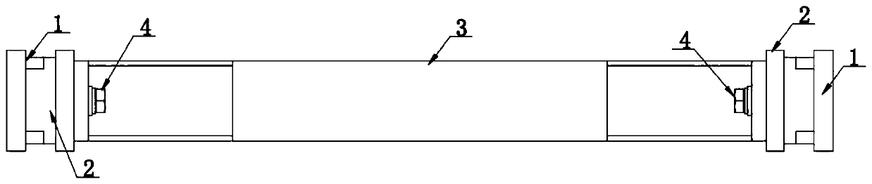
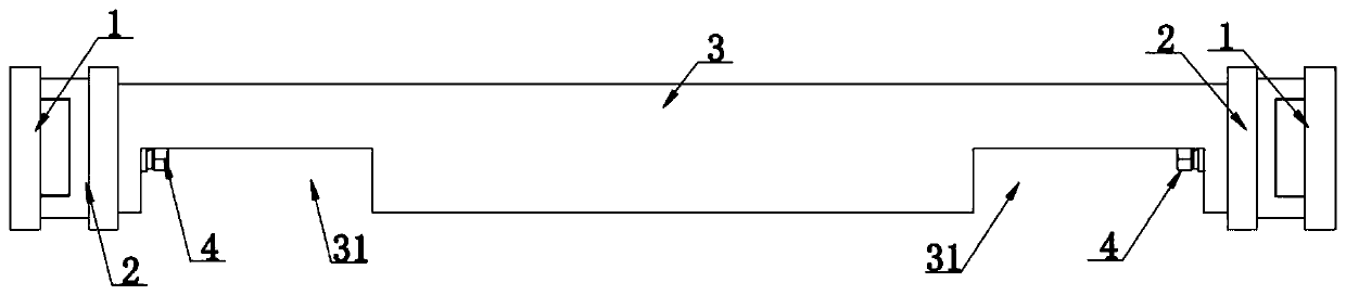
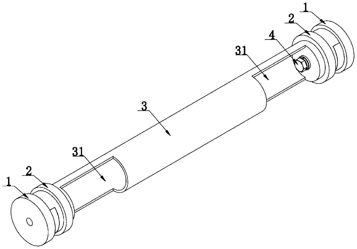
[0037] Such as Figure 1-Figure 7 As shown, a rear axle of a chip removal machine includes a support shaft 3 and a guide wheel assembly respectively arranged at both ends of the support shaft. The guide wheel assembly includes a guide wheel 2 and a fixing seat 1, and the fixing seat 1 is installed on On the machine housing 5, the guide wheel 2 is arranged between the fixed seat 1 and the support shaft 3, and the inner end surface of the fixed seat 1 is provided with a positioning boss 11 for positioning the guide wheel, The outer end surface of the guide wheel 2 is provided with a positioning groove 21 engaged with the positioning boss, the guide wheel 2 is provided with a mounting hole, and the support shaft 3 is provided with a The installation wi...


PUM


Abstract

The invention discloses a rear shaft of chip removal machine. The rear shaft of chip removal machine comprises a supporting shaft and guide wheel assemblies arranged at the two ends of the supportingshaft respectively, each guide wheel assembly comprises a guide wheel and a fixing base, the fixing bases are installed on a chip removal machine shell, the guide wheels are arranged between the fixing bases and the supporting shaft, positioning bosses used for positioning the guide wheels are arranged on the inner end faces of the fixing bases, the outer end face of the guide wheel is provided with a positioning groove matched with the positioning boss in a clamped mode, the interior of the guide wheel is hollow, the supporting shaft is provided with an installation window used for connectingthe supporting shaft with the guide wheel assembly, and the supporting shaft is connected with the fixing base. The rear shaft assembly is of a segmented detachable structure, the structure is simple, maintenance is convenient, the maintenance cost is low, mounting and dismounting are not limited by space, the guide wheel can be mounted, dismounted and replaced conveniently and rapidly in a limited mounting space, the dismounting and mounting efficiency of the rear shaft of the chip removal machine is improved, and therefore the production efficiency of the chip removal machine is improved.

Description

technical field [0001] The invention relates to a rear shaft of a chip removal machine, which belongs to the technical field of machine tool waste chip conveying. Background technique [0002] The chip conveyor is mainly used to collect various metal or non-metal waste chips generated by the machine tool, and transport the waste chips to the equipment in the chip box. The transmission of the existing chip removal machine is mainly through the conveyor chain, the conveyor chain is wrapped around the drive front axle and the chip conveyor rear axle, the drive front axle is provided with a transmission sprocket that cooperates with the conveyor chain, and the chip conveyor rear axle is installed On the rear side of the chip conveyor housing. [0003] The support part of the rear axle of the existing chip removal machine is mostly an integral part formed by round steel bars, and the guide wheel for supporting the conveying chain is fixedly installed on the support part. The gui...

Claims


Application Information

Patent Timeline
IPC IPC(8): B23Q11/00
CPCB23Q11/0042
Inventor 周博尹洪波纪艳青王鑫张哲王文彦周庆学李铁兵
Owner 烟台开发区博森科技发展有限公司
Why Eureka
Try Eureka