A portable password toolbox for power operation
A portable and toolbox technology, applied in the field of portable password toolboxes for electric power operation, can solve the problems of easy theft of maintenance appliances, and achieve the effects of saving physical strength, speeding up transfer and improving work efficiency.
- Summary
- Abstract
- Description
- Claims
- Application Information
AI Technical Summary
Problems solved by technology
Method used
Image
Examples
Embodiment 1
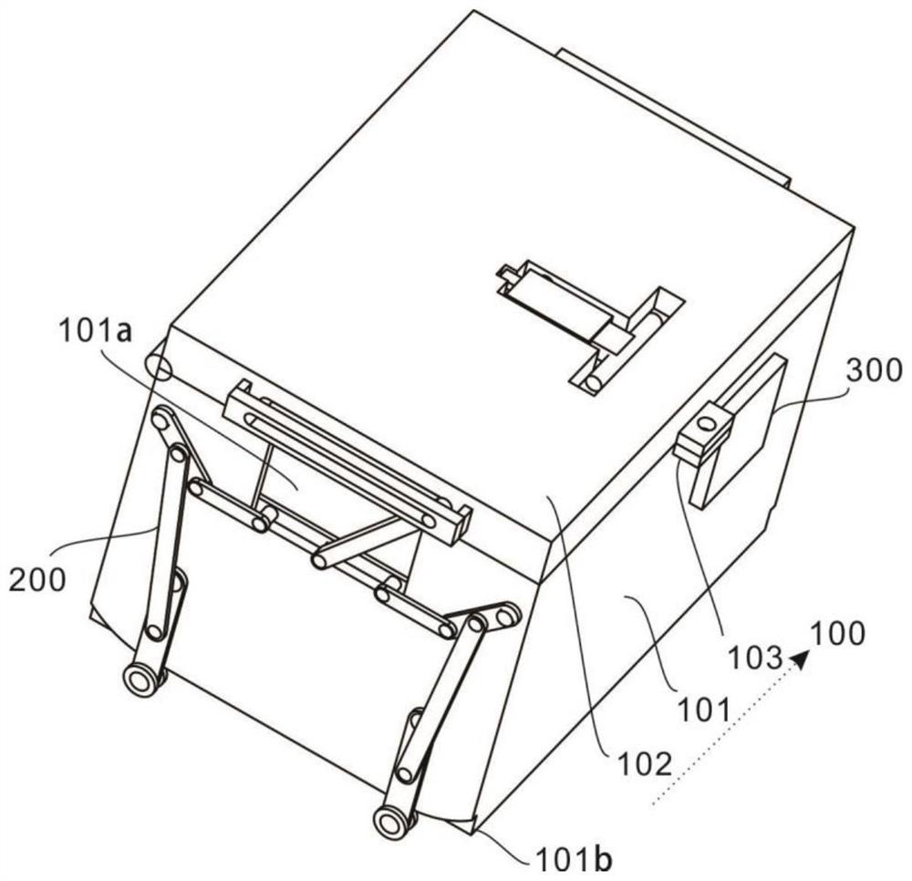
[0033] refer to Figure 1-9 , provides a schematic diagram of the overall structure of a portable password toolbox for power operations, such as figure 1 , a portable password toolbox for electric power operation includes a carrying unit 100 for carrying and protecting maintenance tools, a box body 101 and a top cover 102, an electronic lock 103 for limiting the top cover 102, and an adjustment mechanism for the carrying unit 100. The adjustment unit 200 and the adjustment assembly 201, the password lock unit 300 and the identification assembly 301 for anti-theft protection of the maintenance equipment located in the carrying unit 100; Adjustment, so that the staff do not need to carry the toolbox to carry out the transfer when transferring, and save the physical strength of the staff, but also speed up the transfer speed of the staff, thereby improving the work efficiency of the staff, through the password lock unit 300. Make each Every time the toolbox is opened, the staff ...
Embodiment 2
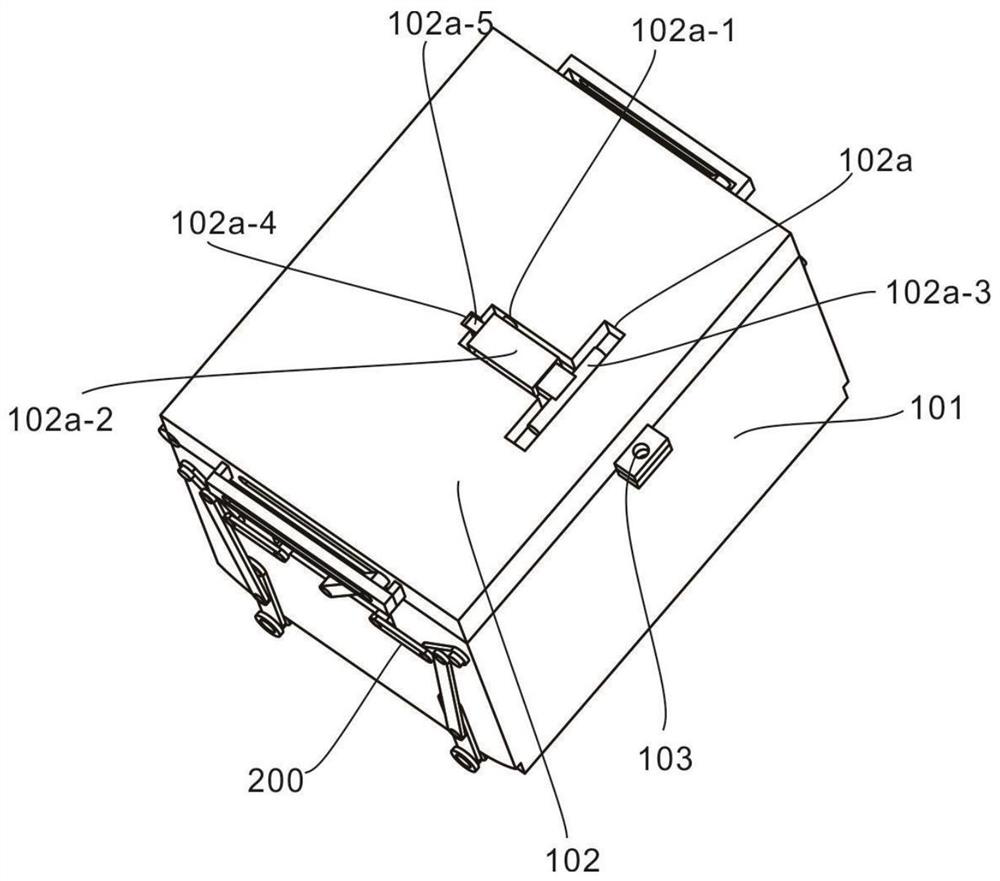
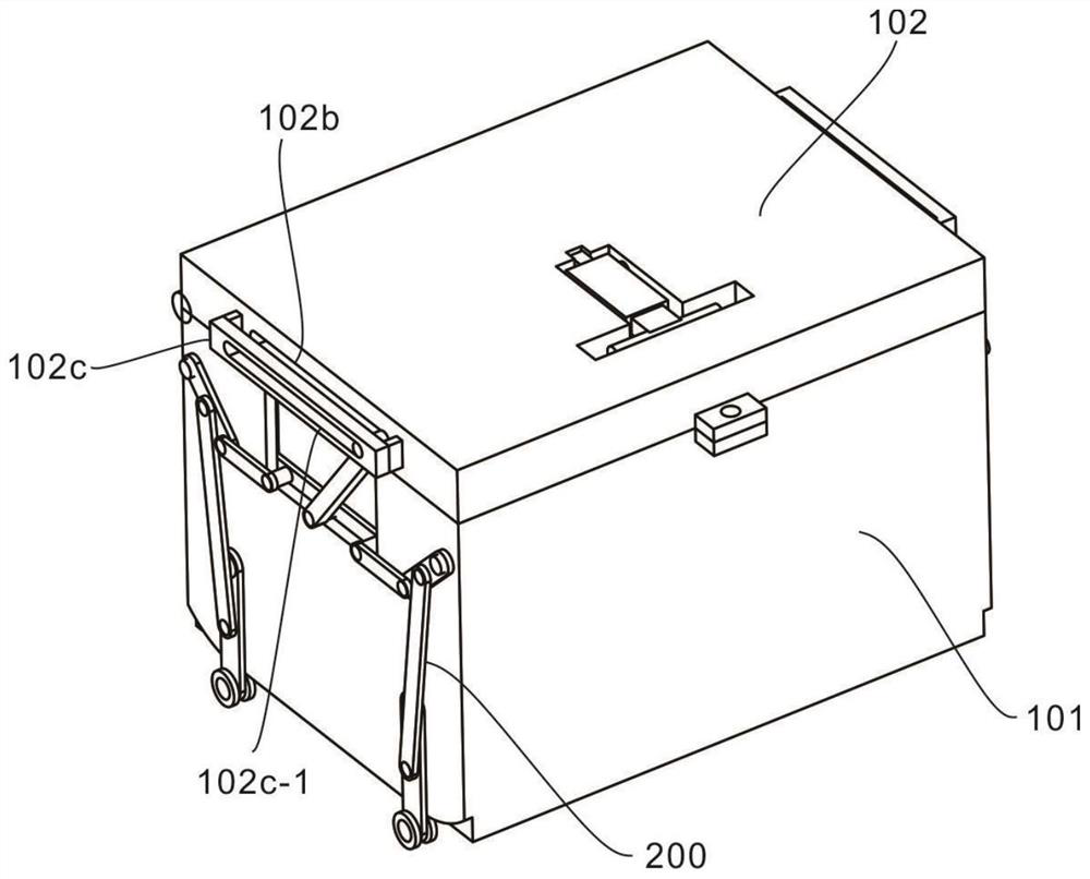
[0036] refer to Figure 2-6, This embodiment is different from the first embodiment in that: the carrying unit 100 for carrying and protecting the maintenance tool also includes a first groove 101a, a second groove 101b and a "T" shape for limiting and accommodating The chute 101c, the first limit rod 101a-1 that acts as a limit, the rotating shaft 101a-2 that enables the pulley 101a-3 to rotate, the pulley 101a-3 that drives the first limit rod 101a-1 to displace, and the The accommodating groove 102a for limiting and accommodating, the first limiting groove 102b, the limiting railing 102c and the second limiting groove 102c-1, the second limiting rod 102a-1 for limiting, and the telescopic sleeve 102a-2, the handle 102a-3 that drives the sleeve 102a-2 to rotate, the arc-shaped limiting groove 102a-4 that limits the position of the first slider 102a-5, and the second position that limits the position of the sleeve 102a-2 A slider 102a-5, a second slider 102b-1 for limiting t...
Embodiment 3
[0042] refer to Figure 7 , This embodiment is different from the above embodiments in that: the adjustment assembly 201 for adjusting the bearing unit 100 also includes a first transmission rod 201a and a transmission block 201b which play a role in rotation, and a first limiter for limiting the transmission block 201b The column 201c, the transmission column 201d and the second transmission rod 201e that play a role in rotation, the second limit column 201f that limits the support rod 201g, the support rod 201g that supports the bearing unit 200, and the universal wheel that drives the displacement of the device 201h.
[0043] Further, by rotating the handle 102a-3, the sleeve 102a-2 is rotated following the handle 102a-3. When the handle 102a-3 is rotated to 90°, the first slider located in the arc-shaped limiting groove 102a-4 102a-5 slides to the end of the arc-shaped limiting groove 102a-4, thereby limiting the handle 102a-3 and the sleeve 102a-2. At this time, the slee...
PUM
 Abstract
Description
Claims
Application Information
 - R&D Engineer
- R&D Manager
- IP Professional
- Industry Leading Data Capabilities
- Powerful AI technology
- Patent DNA Extraction
Browse by: Latest US Patents, China's latest patents, Technical Efficacy Thesaurus, Application Domain, Technology Topic, Popular Technical Reports.
© 2024 PatSnap. All rights reserved.Legal|Privacy policy|Modern Slavery Act Transparency Statement|Sitemap|About US| Contact US: help@patsnap.com


