Eureka AIR delivers breakthrough ideas for toughest innovation challenges, trusted by R&D personnel around the world.

Laser cutting equipment for amorphous alloy and cutting method of laser cutting equipment

An amorphous alloy, laser cutting technology, used in laser welding equipment, metal processing equipment, welding equipment, etc., can solve the problems of troublesome use process, lack of cylindrical alloy limit structure, etc., to improve cutting speed, efficient cooling , Improve the effect of molding quality

Inactive Publication Date: 2021-03-09
王菊
View PDF0 Cites 0 Cited by
  • Summary
  • Abstract
  • Description
  • Claims
  • Application Information

AI Technical Summary

Problems solved by technology

[0004] The purpose of the present invention is to provide a laser cutting equipment and cutting method for amorphous alloys, so as to solve the above-mentioned problem in the background technology that amorphous alloys generally have a square or elongated structure after the overall processing is completed. In order to meet the requirements of special equipment and environment, laser cutting equipment needs to perform segmental slicing operations on cylindrical amorphous alloys. Although existing cutting equipment can stably cut square or elongated alloys, they lack the ability to The limit structure of the cylindrical alloy requires the staff to use the fixture to manually assist the positioning of the alloy material from a distance, which is very troublesome in the actual use process

Method used


Image

  • Laser cutting equipment for amorphous alloy and cutting method of laser cutting equipment
  • Laser cutting equipment for amorphous alloy and cutting method of laser cutting equipment
  • Laser cutting equipment for amorphous alloy and cutting method of laser cutting equipment

Examples


Embodiment Construction

[0031] The following will clearly and completely describe the technical solutions in the embodiments of the present invention with reference to the accompanying drawings in the embodiments of the present invention. Obviously, the described embodiments are only some, not all, embodiments of the present invention. Based on the embodiments of the present invention, all other embodiments obtained by persons of ordinary skill in the art without making creative efforts belong to the protection scope of the present invention.

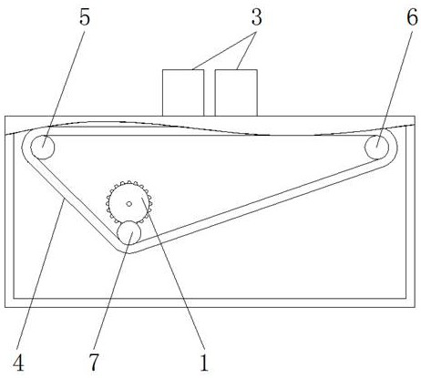
[0032] see Figure 1-9, the present invention provides the following technical solutions: a laser cutting device for amorphous alloys, including a casing 1, a laser component 2, a clamp 3, a conveyor belt 4, a first horizontal roller 5, a second horizontal roller 6, a third Horizontal roller 7, leakage hole 8, ball 9, depression 10, elastic belt 11, roller shaft 12, clamp rod 13, air cavity 14, air pipe 15, socket 16, cavity 17, air hole 18, cavity 19, support...


PUM


Abstract

The invention discloses laser cutting equipment for a amorphous alloy and a cutting method of the laser cutting equipment. The laser cutting equipment comprises a shell and a laser part, wherein the laser part is installed at the top end of the shell, elastic bands are arranged in a clamp and installed on three roll shafts, the surfaces of the elastic bands are made of damping materials and distributed in a triangular state, and a roller shaft is connected to a motor installed on the clamp. According to the laser cutting equipment for the amorphous alloy and the cutting method of the laser cutting equipment, a concave part of a concave arc-shaped structure of a conveying belt is used in cooperation with the elastic bands in the clamp, the cylindrical amorphous alloy can be stably limited through elastic deformation of the elastic bands, and meanwhile, a cut cylindrical workpiece can be in an turning over state at the same time, the cutting speed on the vertical cutting face is increased by a mode of switching different cutting points, and the redesigned conveying belt can be used for conducting efficient cooling operation on the cutting face.

Description

technical field [0001] The invention relates to the technical field of amorphous alloy processing, in particular to a laser cutting device for amorphous alloy and a cutting method thereof. Background technique [0002] As a new material in modern society, amorphous alloy is widely used in industrial production and life because of its excellent structural strength. Amorphous alloy, also known as metallic glass, combines the structural advantages of glass and metal materials. , to solve the problem of traditional glass being fragile, because it is a kind of alloy in essence, so in the process of processing, it is also necessary to use laser equipment to cut and segment it, although the existing similar laser cutting equipment has cutting surfaces The advantages of being flat and without burrs, but there are still the following problems in actual use: [0003] After the overall processing of amorphous alloys, they generally have a square or long strip structure. In order to me...

Claims


Application Information

Patent Timeline
IPC IPC(8): B23K26/38B23K26/70
CPCB23K26/38B23K26/702
Inventor 王菊
Owner 王菊
Why Eureka
Eureka Blog
Learn More