
A kind of light-emitting sheet production equipment and its production process

A technology for producing equipment and light-emitting sheets, applied in welding equipment, metal processing equipment, metal processing and other directions, can solve the problems of low solder drying efficiency, and achieve the effects of shortening drying time, improving service life and convenient replacement.

Active Publication Date: 2022-06-28
赢诺自动机械(上海)有限公司
View PDF10 Cites 0 Cited by
  • Summary
  • Abstract
  • Description
  • Claims
  • Application Information

AI Technical Summary

Problems solved by technology

[0005] In order to improve the defect of low solder drying efficiency, the application provides a light-emitting chip production equipment and its production process

Method used


Image

  • A kind of light-emitting sheet production equipment and its production process
  • A kind of light-emitting sheet production equipment and its production process
  • A kind of light-emitting sheet production equipment and its production process

Examples


Embodiment Construction

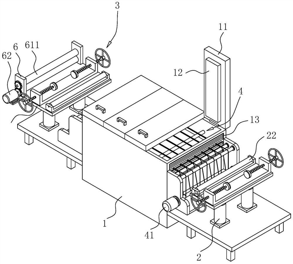
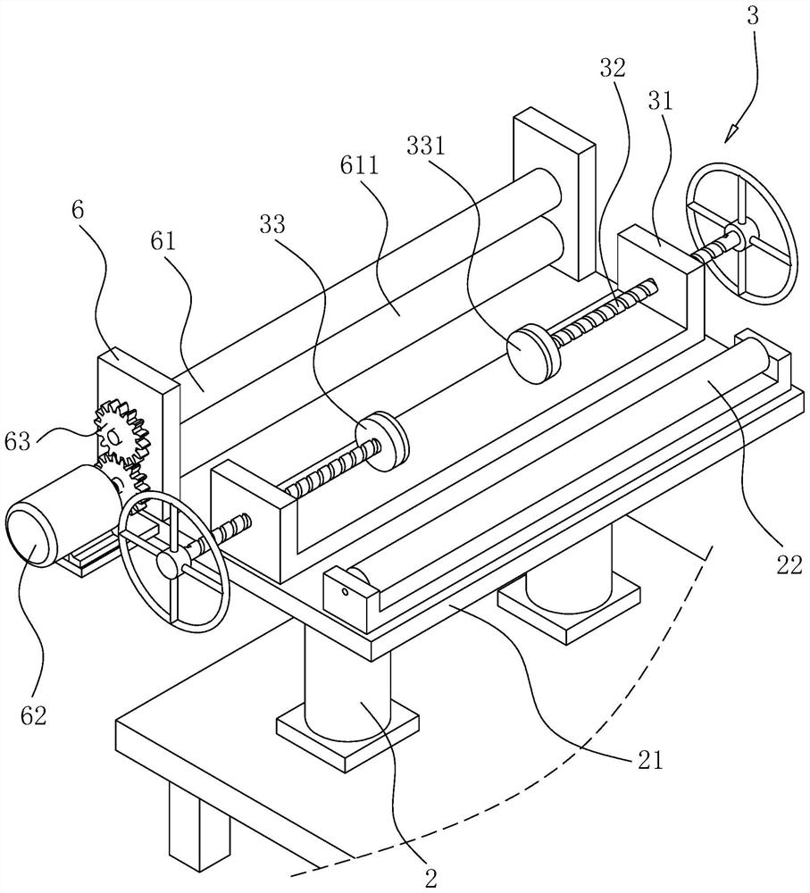
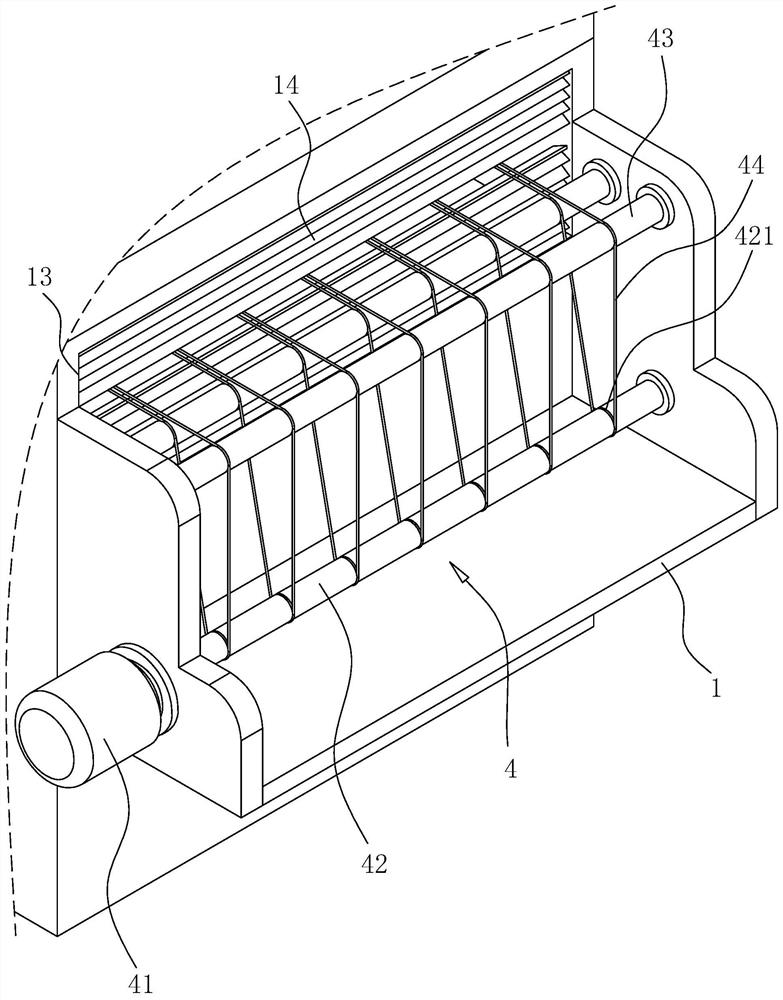
[0041] Attached to the following Figure 1-4 This application will be described in further detail.

[0042] The embodiment of the present application discloses a device for producing a light-emitting sheet.

[0043] refer to figure 1 , a light-emitting sheet production equipment comprises a body 1 with an upper opening, a plurality of mutually abutting cover 11 are hinged on the upper surface of the body 1, the interior of the cover 11 is connected to a closed cavity, and the inner bottom wall of the cover 11 is fixed with heating For the plate 12, the travel direction of the plate and the arrangement direction of the cover 11 are parallel to the length direction of the body 1. Both ends of the body 1 are provided with through holes 13 for the soldered plate to enter and leave the lower part of the cover 11, Both ends of the body 1 in the length direction are provided with lifting components for lifting the board, and the height of the through hole 13 is not lower than the lim...


PUM


Abstract

This application relates to a light-emitting chip production equipment and its production process, which includes a body, the upper surface of the body is hinged with a number of interconnected covers, all the covers are connected to form a closed cavity, and a number of heating plates are fixed on the inner top wall of the cover. The bottom of the inner cavity of the machine cover is provided with a transmission mechanism for assisting the travel of the board, and one end of the body is provided with a through hole for the board and the light strip after the soldering process to enter and pass through, and both ends of the body in the length direction are fixed with Lifting device, the top of the lifting device is fixedly connected with the material receiving plate, and the material receiving plate is rotatably connected with the material receiving roller, the rotation axis of the material receiving roller is perpendicular to the traveling direction of the plate, and the lower surface of the plate is in contact with the top of the material receiving roller. The material plate is provided with a positioning assembly for adjusting the position of the screw material perpendicular to its traveling direction. The height of the through hole is not lower than the rising height of the plate. This application has the effect of improving the efficiency of solder drying.

Description

technical field [0001] The present application relates to the technical field of lamp production, in particular to a light-emitting sheet production equipment and a production process thereof. Background technique [0002] The light-emitting sheet is an important part of the production of the welcome pedal, and the welcome pedal is installed under the car chassis for lighting or decoration. . [0003] The existing drying equipment for the production of luminescent sheets includes a body, and the upper surface of the body is hinged with a plurality of lids that communicate with each other. The interior of all the lids is connected to form a closed cavity. The side wall of the cover is provided with through holes for the circuit board and the light strip after the soldering process to enter and pass; the drying equipment dries the solder at high temperature to make the circuit board and the light strip firmer, and enters the cutting process after drying. . [0004] In view ...

Claims


Application Information

Patent Timeline
Patent Type & Authority Patents(China)
IPC IPC(8): B23K3/00B23K3/08B23P15/00
CPCB23K3/00B23K3/08B23P15/00
Inventor 吴坤杰
Owner 赢诺自动机械(上海)有限公司
Learn More