Main beam ridge forming device for child bicycle
A technology for bicycles and main beams, applied in shearing machine equipment, metal processing equipment, maintenance and safety accessories, etc., can solve the problems of unevenness, time-consuming and laborious, dangerous, etc., and achieve uniform cutting, cutting safety, and waste collection. Save time and effort Effect
- Summary
- Abstract
- Description
- Claims
- Application Information
AI Technical Summary
Problems solved by technology
Method used
Image
Examples
Embodiment 1
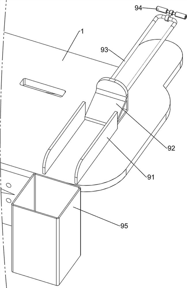
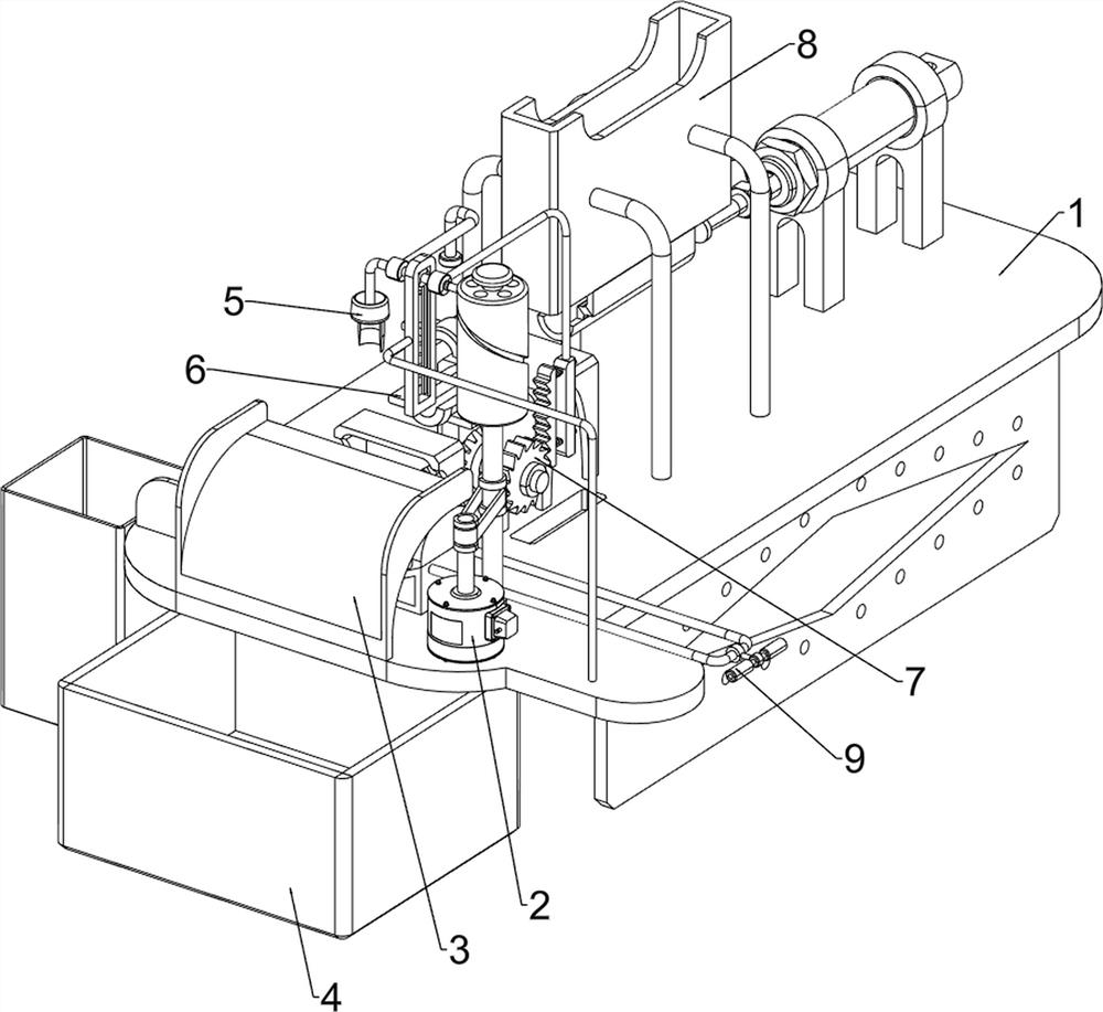
[0071] A main beam ridge opening device for children's bicycles, such as figure 1 , figure 2 and Figure 6As shown, it includes a workbench 1, a motor 2, a slide plate 3, a placement frame 4, a cutting mechanism 5 and a fixing mechanism 6. The motor 2 is installed on the right side of the top front side of the workbench 1, and the slide plate 3 is arranged on the top front side of the workbench 1. , a placement frame 4 is placed on the ground, the placement frame 4 is located below the slide plate 3, a cutting mechanism 5 is provided on the front of the top side of the workbench 1, and the cutting mechanism 5 is connected with the output shaft of the motor 2, and a The fixing mechanism 6 is connected with the cutting mechanism 5 .
[0072] Manual cutting is dangerous, time-consuming and labor-intensive, and uneven. This equipment can cut automatically, which is safe, time-saving and labor-saving, and cuts evenly. First, people put the iron pipe in the fixing mechanism 6, an...
Embodiment 2
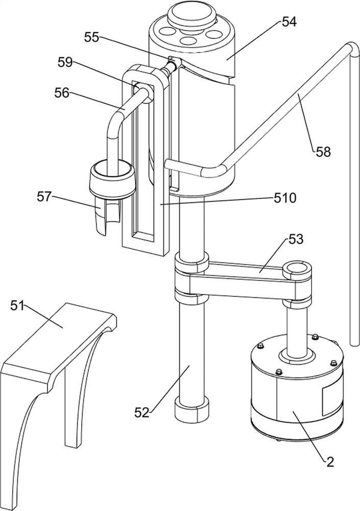
[0074] On the basis of Example 1, such as figure 2 , image 3 and Figure 4 As shown, the cutting mechanism 5 includes a first pallet 51, a first rotating shaft 52, a transmission assembly 53, a special-shaped groove rotating shaft 54, a first slider 55, a first connecting rod 56, a cutting knife 57, a first fixing column 58, Second slide block 59 and slide rail 510, workbench 1 top side front part is provided with first supporting plate 51, and workbench 1 front side right part rotation type is provided with first rotating shaft 52, and the output of first rotating shaft 52 and motor 2 A transmission assembly 53 is connected between the shafts, and the top of the first rotating shaft 52 is provided with a special-shaped groove rotating shaft 54, and the outer side of the special-shaped groove rotating shaft 54 is slidingly provided with a first slider 55, and the right side of the front part of the workbench 1 is provided with a first fixing column 58 , the upper part of...
Embodiment 3
[0079] On the basis of Example 2, such as figure 1 , Figure 4 , Figure 5 and Figure 6 As shown, a turning mechanism 7 is also included. The top side front of the workbench 1 is provided with a turning mechanism 7. The turning mechanism 7 is connected with the second rotating shaft 61 and the first connecting rod 56. The turning mechanism 7 includes a bevel gear set 71, a second A bearing column 72, a third rotating shaft 73, a ratchet gear 74, a ratchet rack 75, a connecting plate 76, a second telescopic assembly 77 and a third connecting rod 78, and the front part of the top side of the workbench 1 is provided with the first bearing column 72, The top of the first bearing column 72 is rotatably provided with a third rotating shaft 73, a bevel gear set 71 is arranged between the second rotating shaft 61 and the third rotating shaft 73, a ratchet gear 74 is arranged on the right side of the third rotating shaft 73, and the first connecting rod 56 The right part is provide...
PUM
 Abstract
Description
Claims
Application Information
 - R&D
- Intellectual Property
- Life Sciences
- Materials
- Tech Scout
- Unparalleled Data Quality
- Higher Quality Content
- 60% Fewer Hallucinations
Browse by: Latest US Patents, China's latest patents, Technical Efficacy Thesaurus, Application Domain, Technology Topic, Popular Technical Reports.
© 2025 PatSnap. All rights reserved.Legal|Privacy policy|Modern Slavery Act Transparency Statement|Sitemap|About US| Contact US: help@patsnap.com


