High-precision four-wire type wire rod tester and testing method thereof

A technology of a wire tester and a test method, which is applied in the direction of short-circuit test, continuity test, and parts of electrical measuring instruments, etc., and can solve problems such as wire damage, wrong pulling and dropping of the tester

Pending Publication Date: 2021-03-05
吉安县众兴电子科技有限公司
View PDF1 Cites 1 Cited by
  • Summary
  • Abstract
  • Description
  • Claims
  • Application Information

AI Technical Summary

Problems solved by technology

[0005] In view of the above situation, in order to overcome the defects of the prior art, the present invention provides a high-precision four-wire wire tester and its testing method, which effectively solves the lack of fixing measures for the wire tester in the above-mentioned background technology. It is easy to fall and cause damage, and at the same time, the detector will accidentally pull the wire during use and cause damage

Method used


Image

  • High-precision four-wire type wire rod tester and testing method thereof
  • High-precision four-wire type wire rod tester and testing method thereof
  • High-precision four-wire type wire rod tester and testing method thereof

Examples


Embodiment 1

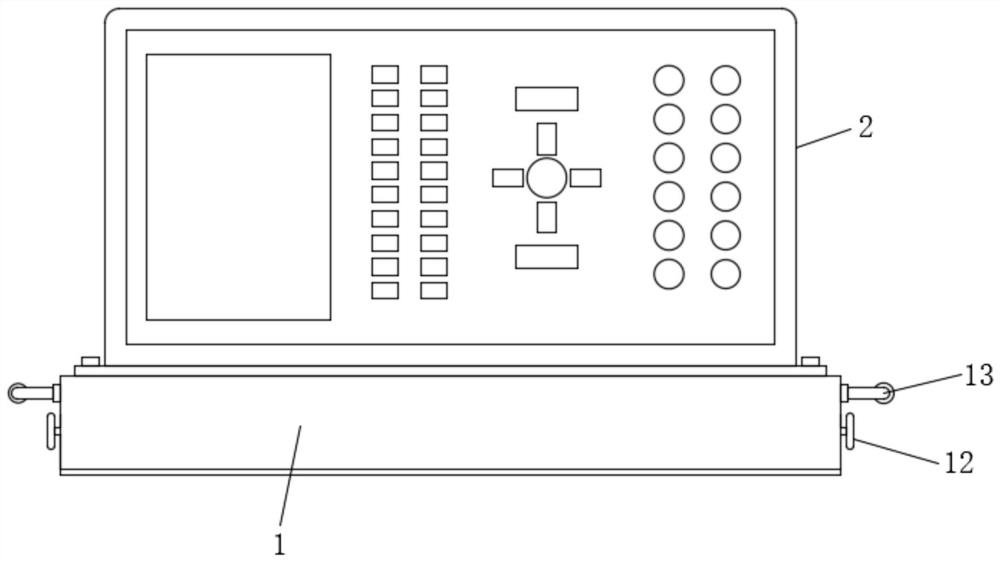
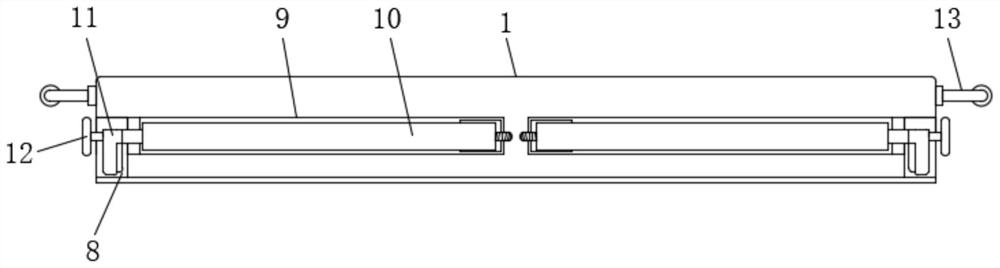
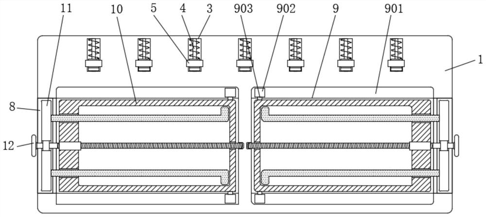
[0033]Example 1Figure 1 to 6It is given, the present invention includes a base 1, and the top of the base 1 is mounted having a tester body 2, one side of the top of the base 1 is equipped with a moving groove 3, and the internal mounting of the moving groove 3 is mounted with a buffer mechanism 4, the buffer mechanism 4 The top is mounted with vertical block 5, and the top of the vertical block 5 is attached to the connection wire fixing mechanism 6, and the tester body 2 is connected to the wire 7, the wire 7 is tensioned at the middle of the connection wire fixing mechanism 6, secured by the connection wire The setting of the mechanism 6 can be effectively tightened and fixed to the wire 7. The lower portion of the base 1 is opened, and the inside of the two card grooves 8 is opened, and the storage chamber 9 is installed. The storage box 10 is provided on one side of the storage cassette 10 and the telescopic frame 11 is attached to the inside of the card groove 8, and the stora...

Embodiment 2

[0034]Embodiment 2. On the basis of the first example,Figure 4 withFigure 6 It is given, the buffer mechanism 4 includes a slider 401, a slider 402, a cushion 403, and a spring 401, and the slider 401 is fixedly mounted inside the moving groove 3, and the slider 402 slides the surface of the slider 401 and sliding the cartridge At the inside of the moving groove 3, the cushion pad 403 is fixed to one side of the slider 402, and the spring 404 is attached to the surface of the slider 401 and is located on the other side of the slider 402, and the vertical block 5 is fixedly mounted on the slider 402. Top, thereby enabling a moving buffer.

Embodiment 3

[0035]Example III, on the basis of an example, byFigure 6 It is given, the connection wire fixing mechanism 6 includes a connecting block 601, a rotating block 602, an elastic hook 603, and a tubular 604, and the connecting block 601 is fixedly mounted on the upper portion of the vertical block 5 side, and one end of the rotating block 602 and the connection block. 601 turning the connection, the elastic hook 603 is fixed to one end of the bottom of the rotary block 602, the snip 604 is fixedly mounted on the other side of the vertical block 5, the elastic hook 603 and the trunk 604 active phase, vertical block 5 The top groove 501 is opened, which can be effectively fixed.


PUM


Abstract

The invention relates to the technical field of wire rod testers, discloses a high-precision four-wire type wire rod tester and a testing method thereof, and solves the problems that a wire rod testerlacks fixing measures and is easy to fall off to be damaged in the use process, and meanwhile, a detector can be damaged by mistakenly pulling a wire in the use process. The tester comprises a base,a tester body is mounted at the top of the base, moving grooves are formed in one side of the top of the base at equal intervals, a buffer mechanism is mounted in each moving groove, a vertical blockis mounted at the top of each buffer mechanism, and a connecting wire fixing mechanism is mounted at the top of each vertical block. The high-precision four-wire type wire rod tester is provided withan effective fixing mechanism, so that the tester can be firmly mounted in use, and meanwhile, the wire rod tester is provided with a mechanism for fixing a wire, so that the wire rod tester can be guaranteed to be safely and stably operated and used; therefore, the high-precision four-wire type wire rod tester can meet the use requirements of people.

Description

Technical field[0001]The present invention belongs to the technical field of wire tester, and is specifically a high precision four-wire wire tester and its test method.Background technique[0002]The wire integrated tester is a start-up automatic diagnosis, automatic correction, and system automatic scanning findings, the system provides advanced breakdown, conduction test, instrument that can be used as a single-sided test, insulation test, etc.[0003]Publication No. CN205958608U's patent application discloses a wire integrated tester of anti-drop damage, the wire integrated tester consists of the following structures: body, shock absorption box, first connecting rod, fixed plate, chute, sliding block, Second connecting rod, buffer rod, buffer box, fixed lever, pin shaft, first spring, partition plate, first buffer chamber, second buffer chamber, extrudate plate, buffer column, buffer rubber pad, buffer, Two spring, handle, non-slip sleeve, roller fixing rod, roller, slide rail; the ...

Claims


Application Information

Patent Timeline
IPC IPC(8): G01R31/52G01R31/54G01R31/58G01R1/04
CPCG01R1/04G01R1/0408G01R31/52G01R31/54G01R31/58
Inventor 陈勇鲁海
Owner 吉安县众兴电子科技有限公司
Why Eureka
Try Eureka