Separate bus bar automatic welding device

An automatic welding and bus bar technology, which is applied in the direction of auxiliary devices, welding equipment, auxiliary welding equipment, etc., can solve the problems of poor bus bar position accuracy, lower product qualification rate, and lower power generation efficiency, so as to improve efficiency and improve welding quality , labor-saving effect

Inactive Publication Date: 2021-03-05
齐河双百数码影像设备有限公司
View PDF0 Cites 0 Cited by
  • Summary
  • Abstract
  • Description
  • Claims
  • Application Information

AI Technical Summary

Problems solved by technology

[0003] Most of the existing welding equipment is to send the glass and the battery string together to the welding equipment, and the bus bar is placed at the welding position of the battery string, and the welding is directly performed on the glass. This method is prone to welding spots, which affects the welding quality and reduces At the same time, most of the bus bars are placed manually, which not only wastes manpower, but also has low efficiency and high production costs
Moreover, the position accuracy of the bus bar is poor, which seriously affects the welding quality and reduces the product qualification rate

Method used


Image

  • Separate bus bar automatic welding device
  • Separate bus bar automatic welding device
  • Separate bus bar automatic welding device

Examples


Embodiment Construction

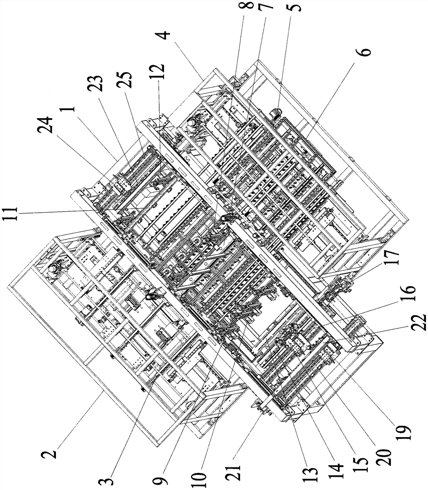
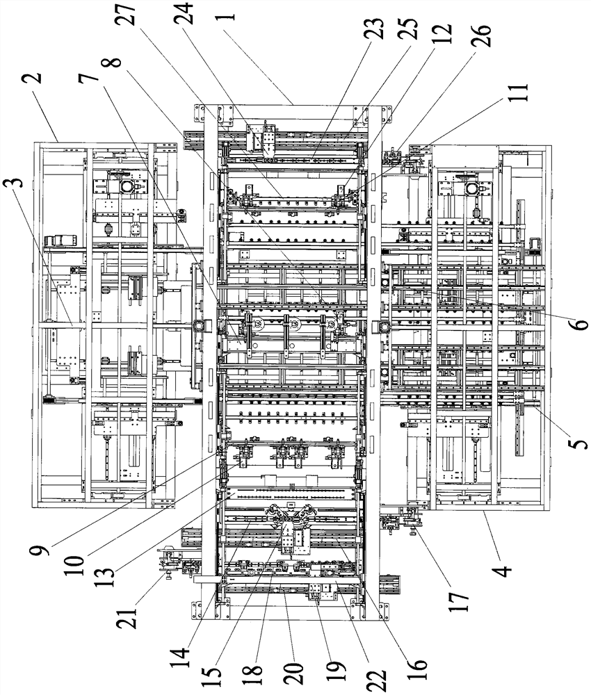
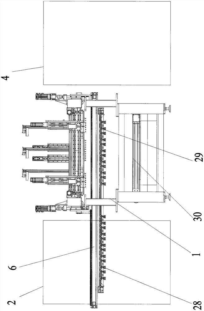
[0026] The following will clearly and completely describe the technical solutions in the embodiments of the present invention with reference to the drawings in the embodiments of the present invention.

[0027] The specific structure is as Figure 1-6 As shown, the separated bus bar automatic welding device includes a frame body 1, a feeding frame 2, an input lifting conveyor belt 3, a discharging frame 4, an output lifting conveyor belt 5, a battery string handling device 6, an intermediate welding head 8, and a complex End welding head 10, simple end welding head 12, front suction nozzle group 28, rear suction nozzle group 29, glass conveyer belt 30, welding station 31, described frame body 1 side is provided with feeding frame 2, and feeding frame 2 is provided with There is an input lifting conveyor belt 3, and the input lifting conveyor belt 3 is used to receive the battery strings and glass to be welded (the battery strings with welding are arranged on the glass), and send...


PUM


Abstract

The invention discloses a separate bus bar automatic welding device. The welding device comprises a frame body, a feeding frame, a discharging frame, a battery string carrying device, middle welding heads, complex end welding heads, simple end welding heads, a glass conveying belt and a welding station, wherein the feeding frame is arranged at one side of the frame body, the discharging frame is arranged at the other side of the frame body, the battery string carrying device is arranged on the upper portion of the frame body, the welding station is arranged at the lower side of the battery string carrying device, the glass conveying belt is arranged at the lower side of the welding station, a moving space is formed in the middle of the battery string carrying device, the middle welding heads fixed to the frame body are arranged in the moving space, the complex end welding heads are arranged at the left side of the welding station, and the simple end welding heads are arranged at the right side of the welding station. According to the welding device, battery strings and glass are separated, and the battery strings are independently welded, so that the welding quality is good; and manpower is saved, and the efficiency is improved.

Description

technical field [0001] The invention relates to the technical field of photovoltaic equipment, in particular to a separate bus bar automatic welding device. Background technique [0002] When producing solar panels, battery strings need to be welded through bus bars. When welding the battery strings, combine the battery strings with the bus bars as required, and then weld them. [0003] Most of the existing welding equipment is to send the glass and the battery string together to the welding equipment, and the bus bar is placed at the welding position of the battery string, and the welding is directly performed on the glass. This method is prone to welding spots, which affects the welding quality and reduces At the same time, most of the bus bars are placed manually, which not only wastes manpower, but also has low efficiency and high production costs. Moreover, the location accuracy of the bus bar is poor, which seriously affects the welding quality and reduces the qualif...

Claims


Application Information

Patent Timeline
IPC IPC(8): B23K37/02B23K37/04B23K37/00B65G47/91H01L31/18H01L21/677
CPCB23K37/00B23K37/0247B23K37/0461B65G47/91H01L21/67742H01L31/188Y02P70/50
Inventor 不公告发明人
Owner 齐河双百数码影像设备有限公司
Why Eureka
Try Eureka