Cooking utensil with liner suction prevention function

A technology of cooking utensils and functions, applied in pressure cookers and other directions, can solve the problems of reducing gas flow speed, slow air intake in exhaust channels, and reducing user experience, so as to reduce energy loss, clear the direction of air conduction, and improve user experience. Effect

Active Publication Date: 2021-03-05
JOYOUNG CO LTD
View PDF5 Cites 0 Cited by
  • Summary
  • Abstract
  • Description
  • Claims
  • Application Information

AI Technical Summary

Problems solved by technology

This pressure cooking appliance has the following defects: the design of the rough surface where the sealing ring is in contact with the inner wall of the inner tank is uneven, and the texture is chaotic, which leads to inconsistent air conduction directions, many dead ends, and poor air intake effect. Moreover, the uneven textured surface will hinder the flow of airflow, causing flow turbulence and energy loss of airflow, reducing the flow speed of gas, making it impossible to achieve rapid air intake, and the negative pressure in the tank cannot be quickly eliminated, making it difficult for users to Open the cover to reduce the user experience; the rough surface of the lower lip and the rough surface of the upper lip are in contact with the position where water vapor is easy to accumulate, which can discharge the air accumulated on the joint surface of the two to form a liquid seal effect, thereby increasing The absorption force between the lower lip and the inner wall of the liner still exists; the contact area between the upper lip and the outer edge of the liner is too large. After pressing up, the upper lip is almost pressed together in a "flat" state On the outer edge of the inner container, this large-area contact increases the suction force between the upper lip and the outer edge of the inner container. When the lid is opened, the upper lip is difficult to be opened by external air and is in a closed state. state, the gas cannot enter, and the negative pressure in the gallbladder cannot be eliminated, and it is difficult to open the lid;
[0004] There is also a kind of cooking equipment in the prior art, which includes a cover body, a float piece and an adjustment device, the float piece is arranged on the cover body, the float piece has an exhaust channel, and the adjustment device can control all According to the opening and closing state of the exhaust passage, when the exhaust passage is opened, the communication between the inside of the cooking equipment and the external environment can be realized to balance the air pressure, and the problem of opening the lid and sucking the pot can be improved, but the structure of the cooking equipment is complicated, and zero in the cover There are many components, the manufacturing cost is high, and the air intake of the exhaust channel is slow during the opening process, so it is impossible to quickly eliminate the negative pressure in the tank

Method used


Image

  • Cooking utensil with liner suction prevention function
  • Cooking utensil with liner suction prevention function
  • Cooking utensil with liner suction prevention function

Examples


Embodiment approach 1

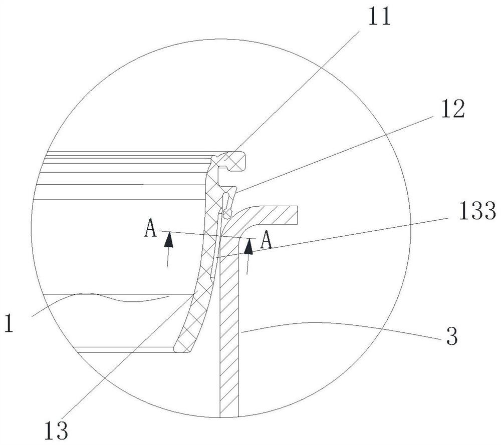
[0062] Embodiment 1, in the first position, the skirt portion 122 abuts against the inner liner 31 of the inner liner 3 , compared with the prior art when the inner liner is closed by the pot lid, the upper lip " As far as the technical solution of sealing is realized by increasing the contact area on the edge of the inner container, the end of the skirt portion 122 in this application abuts against the edge 31 of the inner container for sealing, which can be Sealing is achieved when pressing up, and when the pressure is released, due to the small contact area, the adsorption force between it and the liner edge 31 is reduced, which facilitates the introduction of external air, so as to quickly form a seal between the skirt portion 122 and the liner edge 31 The air intake gap 5.

Embodiment approach 2

[0063] Embodiment 2, such as image 3 As shown, in the first position, the skirt portion 122 abuts against the chamfered portion 32 , and preferably, the cross section of the chamfered portion 32 is arc-shaped. In this embodiment, at the first position, one end of the skirt portion 122 abuts against the chamfered portion 32 , and the arc-shaped chamfered portion 32 can form a stop for the skirt portion 122 , which helps the abutting seal between the free end and the inner wall of the liner 3. Compared with the implementation of abutting against the inner wall of the liner 31, in this embodiment, after the pressure is released, as Figure 6 As shown, under the action of external air, the skirt portion 122 can break away from the contact with the inner container 3 more quickly, and form the air intake gap 5 to facilitate the rapid influx of external air.

[0064] If the sealing ring 1 is applied to a pressure cooker, then as Figure 7 As shown, when the pot cover 2 is fastened...


PUM


Abstract

The invention discloses a cooking utensil with a liner suction prevention function, which comprises a pot body, wherein a liner is arranged in the pot body; and a cooker cover which is provided with asealing ring, wherein the sealing ring comprises a sealing ring body and a lower lip edge, the lower lip edge is provided with an upper sealing part and a lower sealing part, one end of the upper sealing part is fixedly connected with the sealing ring body, the other end of the upper sealing part is fixedly connected with the lower sealing part, and a groove is formed in the side, facing the inner container, of the upper sealing part. A plurality of convex ribs capable of being matched with the inner wall surface of the inner container in a sealing manner are arranged in the groove, and an air guide gap is formed between every two adjacent convex ribs. After the convex rib is pressed upwards in the inner container, sealing can be formed between the convex rib and the inner container underthe action of gas pressure in the inner container, so that the sealing performance of the sealing ring is improved, the convex rib restores to the original shape under the action of elastic force ofthe convex rib after pressure relief, the gas guide gap is opened, and external gas flows into the inner container through the gas guide gap at the moment of cover opening; negative pressure in the container is rapidly eliminated, and rapid uncovering is facilitated.

Description

technical field [0001] The application belongs to the technical field of kitchen appliances, and in particular relates to a cooking appliance with the function of preventing gallbladder absorption. Background technique [0002] The pressure cooking utensils in the prior art generally include a pot body and a pot cover. The pot body is provided with an inner container, and a sealing ring is arranged between the pot cover and the inner container so that the pot cover and the inner container An airtight cooking cavity is formed between the galls. After the cooking is completed, the pressure in the pot is released through the pressure relief valve, and the float on the pot cover falls, and the pressure inside and outside the pot is close to each other. At this time, when the lid opening button is pressed, the pot lid will be delayed to open, and bile suction will occur, that is, The lid and the liner are adsorbed together, resulting in the phenomenon that the lid cannot be open...

Claims


Application Information

Patent Timeline
IPC IPC(8): A47J27/08
CPCA47J27/08
Inventor 朱泽春田海峰
Owner JOYOUNG CO LTD
Why Eureka
Try Eureka