


Quick Research
Generate reliable direction feasibility study reports for your R&D in just a few steps.

Technical Q&A
Discover and master advanced knowledge NOW. Basics, ideas, possibilities, all at once.

Find Solutions
As an expert in R&D theories, this can generate solutions to your technical problems instantly.

Evaluate Feasibility
Analyze your overall solution with one click, know your potential R&D risks in advance.

Monitor Landscape
Get weekly tech updates, stay abreast of the latest tech innovations and key insights.
An inner rotor unipolar motor and motor equipment
A unipolar motor, inner rotor technology, applied in the direction of electromechanical devices, electrical components, electric components, etc., can solve the problems of poor electromagnetic torque performance, low efficiency, large current, etc., to solve the reduction of electromagnetic force, excellent electromagnetic performance, The effect of increasing torque density
- Summary
- Abstract
- Description
- Claims
- Application Information
AI Technical Summary
Problems solved by technology
Method used
Image

Examples
Embodiment 1
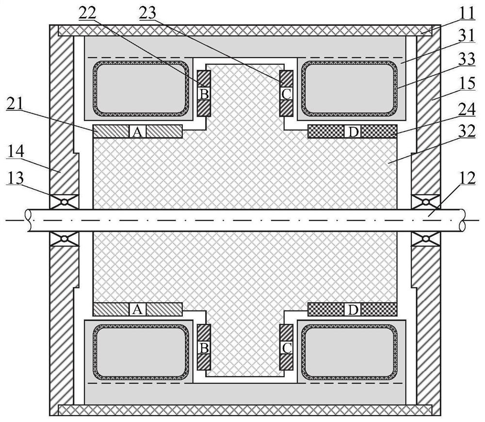
[0042] refer to figure 1 , the inner rotor unipolar motor of this embodiment includes a magnetic unipolar structure A21, a magnetic unipolar structure B22, a magnetic unipolar structure C23, and a magnetic unipolar structure D24. The magnetic unipolar structure A21, magnetic The monopole structure B22, the magnetic monopole structure C23, and the magnetic monopole structure D24 are arranged on the inner rotor 32, and the inner rotor 32 is installed with a rotating shaft 12, and the rotating shaft 12 is arranged with the left end cover 14 and the right end cover 15. Rotationally connected, the left end cover 14 and the right end cover 15 are fixedly connected or integrated through the casing 11. A stator 31 corresponding to the inner rotor 32 is installed in the casing 11, and the stator 31 is connected to the inner rotor 32. An air gap is provided between the inner rotors 32 , and an armature winding 33 is provided in the stator 31 .
[0043] Wherein, the casing 11 is a non-m...
Embodiment 2
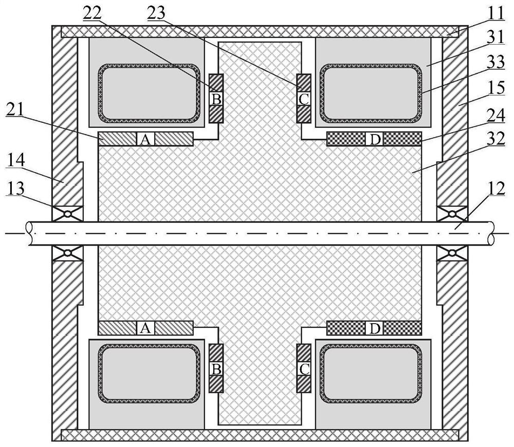
[0049] refer to figure 2 , the inner rotor unipolar motor of this embodiment includes a magnetic unipolar structure A21, a magnetic unipolar structure B22, a magnetic unipolar structure C23, and a magnetic unipolar structure D24. The magnetic unipolar structure A21, magnetic The monopole structure B22, the magnetic monopole structure C23, and the magnetic monopole structure D24 are arranged on the inner rotor 32, and the inner rotor 32 is installed with a rotating shaft 12, and the rotating shaft 12 is arranged with the left end cover 14 and the right end cover 15. Rotationally connected, the left end cover 14 and the right end cover 15 are fixedly connected or integrated through the casing 11. The casing 11 is equipped with a stator 31 corresponding to the inner rotor 32 at both ends of the shaft. The stator 31 An air gap is provided between the inner rotor 32 and the stator 31 is provided with an armature winding 33 .
[0050] Wherein, the casing 11 is a non-magnetic condu...
Embodiment 3
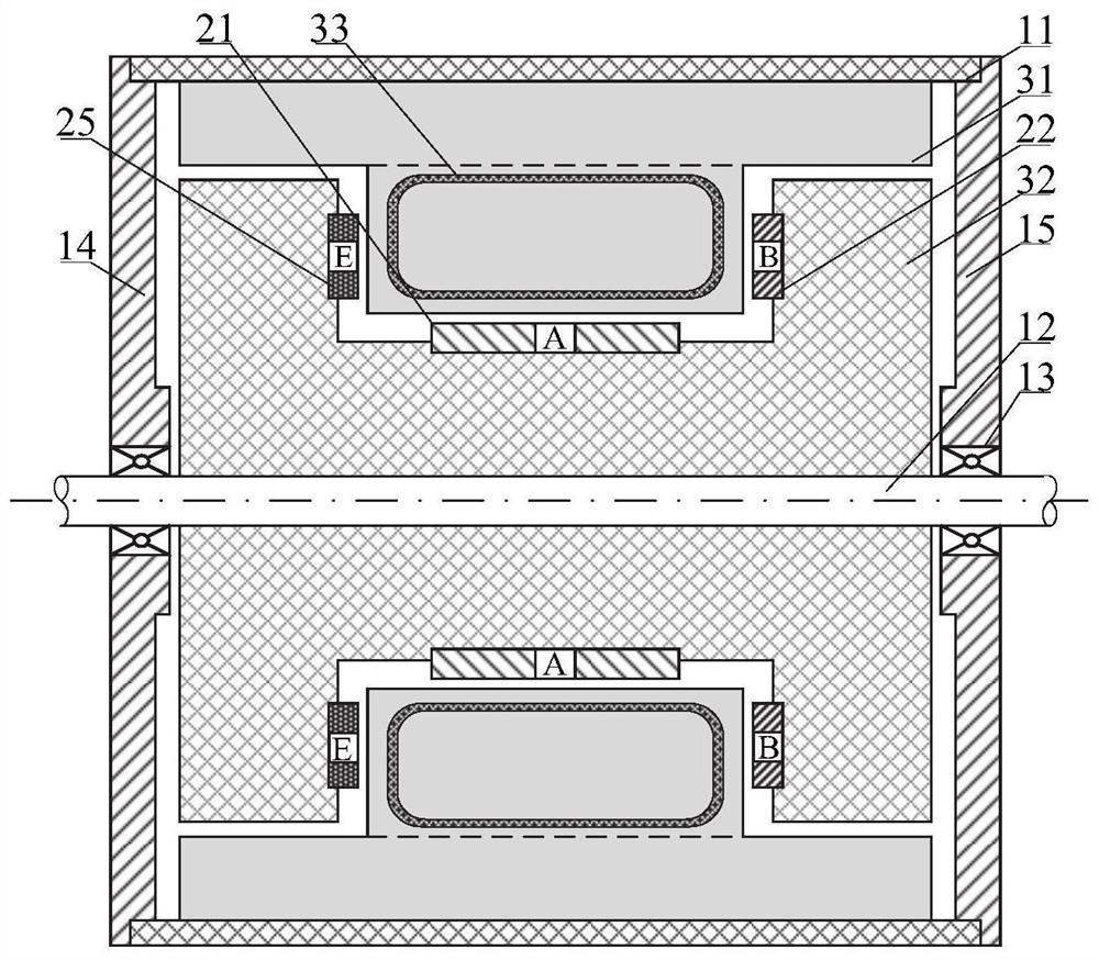
[0056] refer to image 3 , the inner rotor unipolar motor of this embodiment includes a magnetic unipolar structure body A21, a magnetic unipolar structure body B22, and a magnetic unipolar structure body E25, and the magnetic unipolar structure body A21, magnetic unipolar structure body B22, magnetic The unipolar structure E25 is arranged on the inner rotor 32, the inner rotor 32 is equipped with a rotating shaft 12, and the rotating shaft 12 is connected to the left end cover 14 and the right end cover 15, and the left end cover 14 and the right end cover 15 pass through the machine. The housing 11 is fixedly connected or integrated. A stator 31 corresponding to the inner rotor 32 is installed in the housing 11. An air gap is provided between the stator 31 and the inner rotor 32. The inside of the stator 31 An armature winding 33 is provided.
[0057] Wherein, the casing 11 is a non-magnetic conductor.
[0058] It can be understood here that the left end cover 14 and the r...
PUM
 Abstract
Description
Claims
Application Information
 - R&D Engineer
- R&D Manager
- IP Professional
- Industry Leading Data Capabilities
- Powerful AI technology
- Patent DNA Extraction
Browse by: Latest US Patents, China's latest patents, Technical Efficacy Thesaurus, Application Domain, Technology Topic, Popular Technical Reports.
© 2024 PatSnap. All rights reserved.Legal|Privacy policy|Modern Slavery Act Transparency Statement|Sitemap|About US| Contact US: help@patsnap.com