Enhanced heat dissipation device for computer

A technology of a heat sink and a computer, applied in the computer field, can solve the problems of inability to achieve super strong heat dissipation of metal heat sinks, reduce heat dissipation efficiency of metal heat sinks, etc., and achieve the effects of being conducive to cooling and heat dissipation, reducing corrosive effects and improving efficiency.

Active Publication Date: 2021-03-02
枣庄科顺数码有限公司
View PDF6 Cites 0 Cited by
  • Summary
  • Abstract
  • Description
  • Claims
  • Application Information

AI Technical Summary

Problems solved by technology

[0002] In the environment where the computer works for a long time, it needs to carry out heat dissipation and exhaust to remove the heat in the chassis. The water cooling and heat dissipation of the computer in the prior art is generally designed relatively simple, and there are often the following technical defects in the process of use. The first cycle The water device is placed in the chassis, which causes the heat generated by the computer to work for a long time to easily heat the water circulation body, and the water circulation at this time reduces the heat dissipation efficiency of the metal heat sink in the chassis. Second, the design of the water circulation heat dissipation pipe It is relatively simple. It is only bonded with the metal heat sink to take away the heat on the surface of the metal heat sink. It cannot achieve super-strong heat dissipation with high efficiency and air jet on the metal heat sink.

Method used


Image

  • Enhanced heat dissipation device for computer
  • Enhanced heat dissipation device for computer
  • Enhanced heat dissipation device for computer

Examples


Embodiment Construction

[0031] The technical solutions in the embodiments of the present invention will be clearly and completely described below with reference to the accompanying drawings in the embodiments of the present invention. Obviously, the described embodiments are only a part of the embodiments of the present invention, but not all of the embodiments. Based on the embodiments of the present invention, all other embodiments obtained by those of ordinary skill in the art without creative efforts shall fall within the protection scope of the present invention.

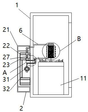
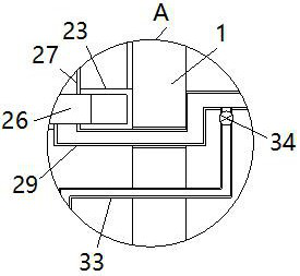
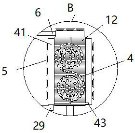
[0032] see Figure 1-7, the present invention provides a technical solution: an enhanced heat dissipation device for a computer, comprising a chassis 1, an organic body 11 is fixedly installed in the cavity of the chassis 1, a heat dissipation metal piece 12 is fixedly installed on the top of the body 11, the body 11 and the heat dissipation metal piece 12 are the prior art, and will not be repeated here. The left side wall of the cab...


PUM


Abstract

The invention relates to the technical field of computers, and discloses an enhanced heat dissipation device for a computer, the enhanced heat dissipation device comprises a case, a machine body is fixedly installed in a case cavity, a heat dissipation metal piece is fixedly installed at the top of the machine body, and a water circulation device is arranged on the left side wall surface of the case and comprises a first water ring pipe and a water pump. According to the enhanced heat dissipation device for the computer, by arranging the water circulation device, dynamic circulation of water in cavities of the first water ring pipe, the second water ring pipe, the third water ring pipe, the first cooling pipe and the second cooling pipe is achieved, and the dynamically-circulated water dissipates heat in the first water ring pipe, the second water ring pipe and the third water ring pipe in the cavity of the computer case; water after heat dissipation is injected into the cavities of the first cooling pipe and the second cooling pipe through the drainage pipe to cool the heat dissipation metal part in a contact mode, so that heat on the heat dissipation metal part is directly takenaway, the cooling and heat dissipation efficiency of the computer body is improved, and the purpose of strengthening heat dissipation is achieved.

Description

technical field [0001] The invention relates to the technical field of computers, in particular to an enhanced heat dissipation device for computers. Background technique [0002] In the environment where the computer works for a long time, it is necessary to conduct heat dissipation and exhaust air to remove the heat in the chassis. The water-cooled heat dissipation design of the computer in the prior art is generally relatively simple, and there are often the following technical defects in the process of use. The first cycle The water device is placed in the chassis, which causes the heat generated by the computer to work for a long time to easily heat the water circulation body, and the water circulation at this time reduces the heat dissipation efficiency of the metal heat sinks in the chassis. Second, the design of the water circulation cooling water pipe It is relatively simple. It only attaches to the metal heat sink to take away the heat on the surface of the metal p...

Claims


Application Information

Patent Timeline
IPC IPC(8): G06F1/20G06F1/18
CPCG06F1/20G06F1/183
Inventor 杨春林
Owner 枣庄科顺数码有限公司
Why Eureka
Try Eureka