an optical machine

An optical machine and light source technology, applied in optics, instruments, projection devices, etc., can solve problems affecting the energy utilization rate of the projection system, projection uniformity, projection quality, reduced reliability of the optical machine, and reduced service life of the optical machine. Achieve the effect of facilitating independent heat dissipation, reducing the probability of short circuit, and reducing the error of optical path propagation

Active Publication Date: 2022-07-22
SHENZHEN ANHUA OPTOELECTRONICS TECH
View PDF0 Cites 0 Cited by
  • Summary
  • Abstract
  • Description
  • Claims
  • Application Information

AI Technical Summary

Problems solved by technology

It can be seen that DLP projectors are optical precision equipment. When an error occurs in a certain part of the optical path, the subsequent optical path propagation deviation will be amplified, or the light source utilization rate will be reduced, which directly affects the energy utilization rate of the entire projection system. Uniformity, projection quality, etc.
[0004] In order to pursue the miniaturization of DLP projectors, the size of DLP optical machines is getting smaller and smaller. However, due to the compact and rigorous structure of optical machines, the process of reducing the size will lead to poor heat dissipation and even short circuits. That is to say, the reliability of the optical machine is reduced, which will lead to the reduction of the service life of the optical machine.

Method used


Image

  • an optical machine
  • an optical machine
  • an optical machine

Examples


Embodiment Construction

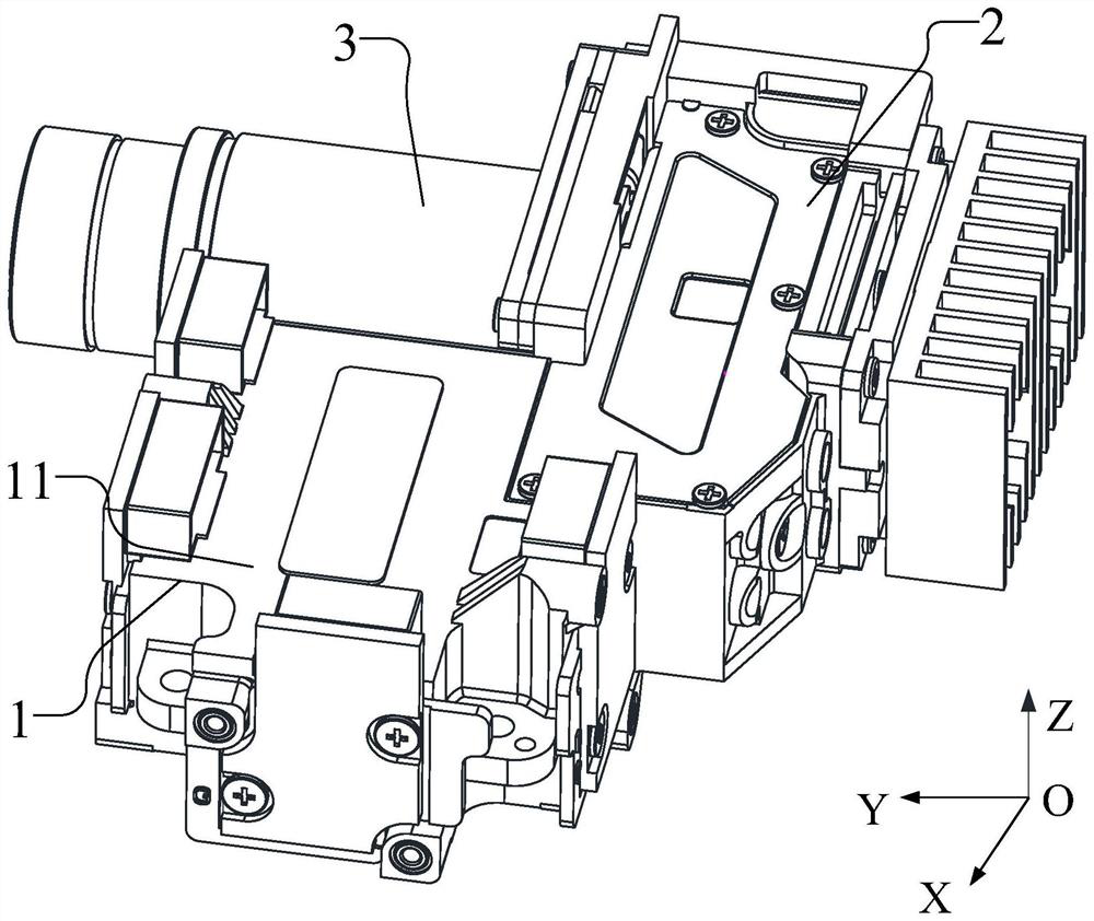
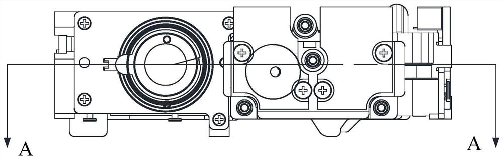
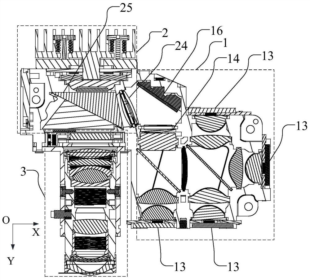
[0029] In order to ensure the reliability of the operation of the optomechanical under the premise of miniaturization of the optomechanical, this embodiment discloses an optomechanical. Please refer to figure 1 , figure 2 and image 3 ,in, figure 1 It is a schematic diagram of a front-view three-dimensional structure of an opto-mechanical disclosed in this embodiment, figure 2 It is a left-view structural schematic diagram of an opto-mechanical disclosed in this embodiment, image 3 for figure 2 Schematic diagram of the cross-sectional structure in A-A.

[0030] Please refer to figure 1 , figure 2 and image 3 The optical machine disclosed in this embodiment includes: a light source optical path lens group module 1, a light modulation system module 2 and a projection optical path lens group module 3, wherein the lens group of the light source optical path provides incident light to the light modulation system, and the light source can be RGB light-emitting Diode; t...


PUM


Abstract

The invention discloses an optical machine, comprising: a light source optical path lens group provides incident light to a light modulation system, the light modulation system performs light processing on the light source and then exits through a projection optical path lens group to project onto a projection plane, a light source optical path lens group module , the light modulation system module and the projection light path lens group module are arranged horizontally, the light source light path lens group module has an integrally formed top wall, the top wall is made of non-metallic material, and the light source wiring terminals are arranged on the top wall; the light source light path lens group module There is a first opening facing the negative direction of the Z-axis; the light modulation system module has a second opening facing the positive direction of the Z-axis; wherein, the projection of the first opening on the XOY plane and the projection of the second opening on the XOY plane The projections do not overlap; the upper cover and the upper cover are made of metal. Therefore, the probability of short circuit of the light source optical path lens group module is reduced; and at the same time, the upper cover plate is made of metal material, which can dissipate heat from the light modulation system module.

Description

technical field [0001] The invention relates to the technical field of DLP projection, in particular to an optical machine. Background technique [0002] Micro projection technology is a new type of modern projection display technology. It gradually penetrates into people's daily life by realizing the miniaturization and portability of equipment, and has gradually become an important development trend of projection display. The Digital Light Processing (DLP) projection display method has the characteristics of high brightness, high contrast and high resolution. Combined with the new LED light source, it realizes a miniaturized portable micro-projection, which satisfies people's portable and free projection display. demand. [0003] The projected image quality of a DLP projector is closely related to the optical path and the way the optical components are fixed. In DLP projectors, three-color (R, G, B) diodes (LEDs) are often used as light sources, in which the R, G, B diod...

Claims


Application Information

Patent Timeline
Patent Type & Authority Patents(China)
IPC IPC(8): G03B21/00G03B21/14G03B21/16G03B21/20
CPCG03B21/005G03B21/142G03B21/16G03B21/145G03B21/206G03B21/2066
Inventor 高怡玮吴积涛程炎孙峰
Owner SHENZHEN ANHUA OPTOELECTRONICS TECH
Why Eureka
Try Eureka