Flue gas distributor

A distributor and flue gas technology, which is applied in heat exchanger shells, lighting and heating equipment, heat exchange equipment, etc., can solve problems such as insufficient utilization of high-temperature flue gas, local burns of heat exchange tubes, etc.

Inactive Publication Date: 2021-03-02
WUXI XIZHOU MACHINERY
View PDF11 Cites 0 Cited by
  • Summary
  • Abstract
  • Description
  • Claims
  • Application Information

AI Technical Summary

Problems solved by technology

[0004] Therefore, the technical problem to be solved by the present invention is to overcome the defects of insufficient utilization of high-temperature flue gas in the prior art and easy local burns on the heat exchange tubes, thereby providing a flue gas distributor

Method used


Image

  • Flue gas distributor

Examples


Embodiment Construction

[0015] In order to make the object, technical solution and advantages of the present invention clearer, the present invention will be further described in detail below in conjunction with the accompanying drawings and embodiments. It should be understood that the specific embodiments described here are only used to explain the present invention, not to limit the present invention.

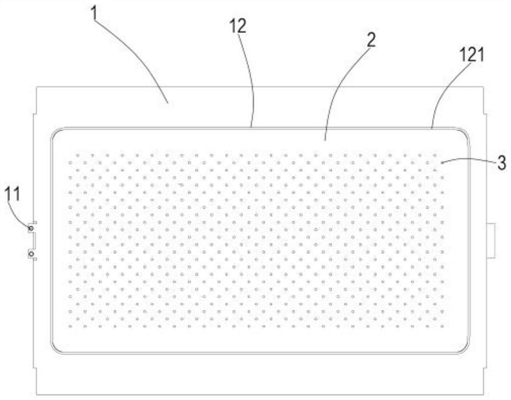
[0016] see figure 1 , a smoke distributor, comprising a fixed plate 1, a smoke distribution plate 2 and a through hole 3 located on the smoke distribution plate 2. The smoke distribution plate 2 is located in the middle of the fixing plate 1 , and the through holes 3 are set through the smoke distribution plate 2 .

[0017] see figure 1 , the fixed plate 1 is arranged in a rectangular parallelepiped shape. In one embodiment, fixing devices 11 are respectively provided on both sides of the fixed plate 1 in the longitudinal direction, and the fixing devices 11 are used to adjust the position of the...


PUM


Abstract

The invention relates to the technical field of heat exchanger equipment parts, in particular to a flue gas distributor. The flue gas distributor aims to solve the problem of waste caused by insufficient fuel utilization rate in the prior art. The flue gas distributor is characterized by comprising a fixed plate, a flue gas distribution plate is arranged on the fixed plate, a plurality of throughholes are formed in the flue gas distribution plate, the through holes are used for homogenizing flue gas, and the flue gas distribution plate and the fixed plate are integrally formed. Through the arrangement of the through holes in the flue gas distribution plate, the whole stream of high-temperature flue gas is uniformly distributed, the impact force of the high-temperature flue gas is reduced,the local heating of a heat exchange pipe can be effectively prevented, and the heat released by the combustion of fuel gas is fully absorbed, so that the fuel utilization rate is improved, the purpose of improving the heat conversion efficiency of key parts of a heating system is achieved, the heat exchange pipe is prevented from being burnt and damaged due to local heating, the service life ofthe heat exchange pipe is effectively prolonged, meanwhile, the maintenance cost of a user is reduced, and the cost is saved.

Description

technical field [0001] The invention relates to the technical field of heat exchanger parts, in particular to a flue gas distributor. Background technique [0002] Usually, the heat exchanger generally includes a heat exchange tube and a combustion chamber located below the heat exchange tube. The high-temperature flue gas adheres to the inner wall of the heat exchange tube and liquefies to form condensed water, thereby releasing heat. [0003] In the heat exchanger in the prior art, the flue gas pipe is directly connected to the combustion chamber, and the hot gas generated after fuel combustion passes through the pipe directly to the components of the heating system. and because the high-temperature flue gas is a whole stream of flue gas with a certain impact force, it is easy to cause damage to the heat exchange tube. At the same time, during the heat exchange process, only the part of the heat exchange tube close to the pipe is heated. It is easy to cause burns to the ...

Claims


Application Information

Patent Timeline
Patent Type & Authority Applications(China)
IPC IPC(8): F28F9/22F28F9/26
CPCF28F9/22F28F9/26F28F2009/222
Inventor 包建忠顾达标王正阳
Owner WUXI XIZHOU MACHINERY
Why Eureka
Try Eureka