Alternating current charging pile with take-up structure

An AC charging pile and charging pile technology, applied in charging stations, electric vehicle charging technology, electrostatic separation, etc., can solve the problems of poor external anti-interference ability, single structure, loose internal connection, etc., to improve isolation protection ability, avoid Messy, wrinkle-free aging effect

Active Publication Date: 2021-03-02
HESHENG (SHANDONG) INTELLIGENT IND TECH RES INST CO LTD
View PDF9 Cites 2 Cited by
  • Summary
  • Abstract
  • Description
  • Claims
  • Application Information

AI Technical Summary

Problems solved by technology

[0003] After retrieval, China Patent Network discloses a charging pile with a take-up structure (public announcement number CN108544964A), through the main casing, cables and charging guns that are movably inserted on the main casing, and the main casing has a take-up wire cavity, the main shell is provided with a wire outlet connected to the wire receiving chamber, and a wire receiving column assembly for retracting and releasing the cable that can rotate around its own axis is provided in the wire receiving chamber. One end of the cable is connected to the charging gun, and the wire The other end of the cable passes through the wire outlet and is wound on the take-up post assembly, and the end of the cable wound on the take-up post assembly passes through the take-up post assembly and is fixed at the bottom of the main housing. The column assembly realizes the adjustment of cable length and the storage and recovery of cables. The structure is simple to use and can effectively avoid cable wear and leakage. However, the structure of this type of device is relatively simple. During use, the anti-interference ability to the outside world is poor. And the winding method is relatively rough, and its winding method can easily damage the internal structure of the cable, resulting in wrinkles and breakage of the cable and loose internal connections

Method used


Image

  • Alternating current charging pile with take-up structure
  • Alternating current charging pile with take-up structure
  • Alternating current charging pile with take-up structure

Examples


Embodiment Construction

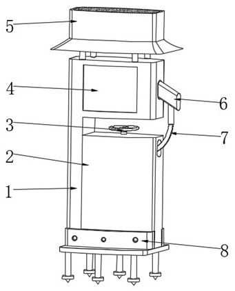
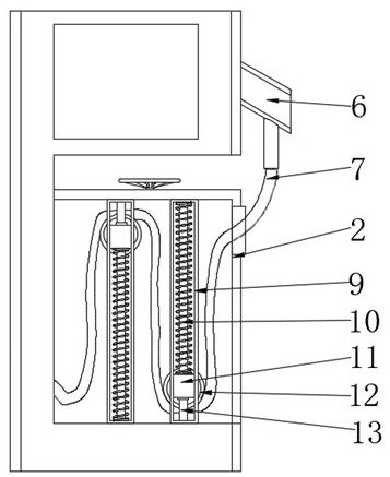
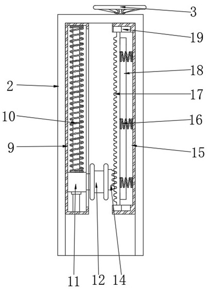
[0024] see Figure 1~6 , in an embodiment of the present invention, an AC charging pile with a wire-receiving structure includes a charging pile body 1, and a mounting mechanism 8 is engaged under the charging pile body 1. The mounting mechanism 8 includes a mounting chassis 81, and the mounting chassis 81 The top of the positioning card seat 82 is provided with a positioning card seat 82, and the front and rear sides of the positioning card seat 82 are symmetrically provided with positioning screw holes 83, and the bottom of the installation chassis 81 is symmetrically fixed with an anchoring cone rod 84, and the bottom end of the anchoring cone rod 84 is provided with a stop position. The convex ring 85, the number of anchoring cone rods 84 shall not be less than two groups, each group shall not be less than three, and the length of the anchoring cone rods 84 shall not be less than 30cm. During the installation and use of the charging pile, the staff will install the bottom f...


PUM

PropertyMeasurementUnit
lengthaaaaaaaaaa

Abstract

The invention relates to the technical field of charging piles, and discloses an alternating current charging pile with a take-up structure. The alternating current charging pile is characterized in that an installation mechanism is clamped to the lower part of a charging pile body; a dust removal mechanism is fixedly connected to the upper part of the charging pile body; a take-up mechanism is arranged at the position, located at the bottom end, of the inner side of the charging pile body; a charging cable is connected to the position, located at the bottom end, of one side of the charging pile body; and a charging gun is arranged at the top end of the charging cable. According to the alternating current charging pile, the ground surface is anchored and positioned through the installationmechanism, the charging pile can be firmly positioned and supported, meanwhile, through circulating air blowing of the dust removal mechanism to the charging pile, the situation that the charging pile is messy and seriously corroded due to the fact that external dust is scraped and scattered on the charging pile can be avoided, and in the using process, the charging cable is wound in a folded mode through the take-up mechanism, a traditional surrounding winding mode is replaced, and the situation that the charging cable is wrinkled, aged and loosened in internal connection in the long-term winding process can be avoided.

Description

technical field [0001] The invention relates to the technical field of charging piles, in particular to an AC charging pile with a take-up structure. Background technique [0002] Charging piles can be divided into DC charging piles, AC charging piles and AC-DC integrated charging piles, which can be fixed on the ground or walls, and installed in public buildings (public buildings, shopping malls, public parking lots, etc.) and residential area parking lots or charging stations , can charge various models of electric vehicles according to different voltage levels. [0003] After retrieval, China Patent Network discloses a charging pile with a take-up structure (public announcement number CN108544964A), through the main casing, cables and charging guns that are movably inserted on the main casing, and the main casing has a take-up wire cavity, the main shell is provided with a wire outlet connected to the wire receiving chamber, and a wire receiving column assembly for retra...

Claims


Application Information

Patent Timeline
Patent Type & Authority Applications(China)
IPC IPC(8): B65H75/38B65H75/44B65H75/48B60L53/31B01D46/12B03C3/00B03C3/34
CPCB65H75/38B65H75/4457B65H75/48B60L53/31B01D46/12B03C3/00B03C3/34B65H2701/34Y02T90/12
Inventor 毛文池刘新昌周鸿成李朋朋吕振辉
Owner HESHENG (SHANDONG) INTELLIGENT IND TECH RES INST CO LTD
Why Eureka
Try Eureka