A riveting tooling for riveted circuit boards used in the PCB pressing process

A pressing process and circuit board technology, applied in the direction of rivets, screws, threaded fasteners, etc., can solve the problems of large mold loss, product piercing copper foil, circuit board depression, etc., to achieve strong positioning support and enhanced riveting Combined effect, the effect of solving the problem of layer deviation

Active Publication Date: 2020-01-07
昆山敏欣电子有限公司
View PDF9 Cites 0 Cited by
  • Summary
  • Abstract
  • Description
  • Claims
  • Application Information

AI Technical Summary

Problems solved by technology

[0004] In the prior art, during the riveting process of the rivet, the mold loss is large, the rivet produces more chips during the riveting process, and the layer deviation phenomenon is serious, which will cause the pressed product to puncture the copper foil and cause the circuit board to sag , steel plate deformation, short circuit and other high scrap phenomenon, resulting in poor yield

Method used


Image

  • A riveting tooling for riveted circuit boards used in the PCB pressing process
  • A riveting tooling for riveted circuit boards used in the PCB pressing process
  • A riveting tooling for riveted circuit boards used in the PCB pressing process

Examples


Embodiment Construction

[0025] Specific embodiments of the present invention will be described in detail below in conjunction with the accompanying drawings. It should be understood that the specific embodiments described here are only used to illustrate and explain the present invention, and are not intended to limit the present invention.

[0026] For the convenience of description, spatially relative terms may be used here, such as "on ...", "over ...", "on the surface of ...", "above", etc., to describe the The spatial positional relationship between one device or feature shown and other devices or features. It will be understood that the spatially relative terms are intended to encompass different orientations of the device in use or operation in addition to the orientation depicted in the figures. For example, if the device in the figures is turned over, devices described as "above" or "above" other devices or configurations would then be oriented "beneath" or "above" the other devices or conf...


PUM


Abstract

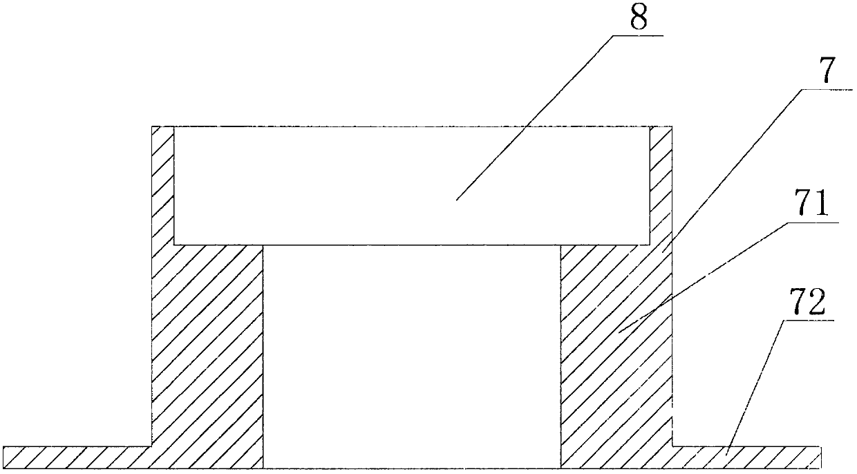
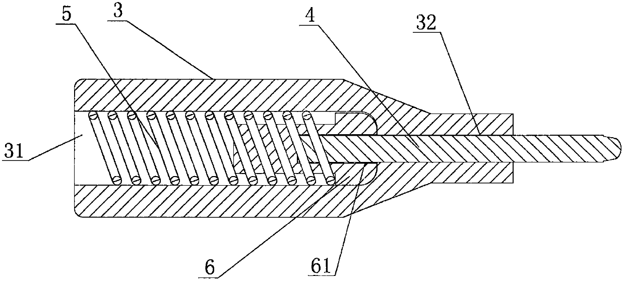
The invention discloses a blind rivet. The rivet includes a rivet body and a cavity located in the rivet body. The rivet body includes a cylinder and a base extending outward from one end of the cylinder. The cavity is composed of coaxial steps. The hole is formed, and the diameter of the cavity near the end of the base is smaller than the diameter near the end of the cylinder. The non-blooming mold of the above-mentioned non-blooming rivet includes an upper mold and a lower mold. The upper mold includes an upper mold shell and an upper punch. One section of the upper mold shell is provided with an upper inner cavity, and the other section is provided with The upper through hole connected to the inner cavity, the upper punch passes through the upper inner cavity and extends out of the upper through hole; the lower mold includes a lower mold shell, a lower punch needle and a spring, and a section of the lower mold shell is provided with a lower mold shell. The inner cavity, the other section is provided with a lower through hole communicating with the lower inner cavity, the lower punching needle extends into the lower inner cavity through the lower through hole, and the spring is arranged in the lower inner cavity. The non-blooming rivet and the non-blooming mold of the present invention have the advantages of no deformation and strong positioning and supporting force.

Description

technical field [0001] The invention relates to the technical field of rivet processing and manufacturing, in particular to a non-blooming rivet and a non-blooming mold thereof. Background technique [0002] Rivets are one of the most commonly used fasteners for structural connections that are not expected to be disassembled. It is generally composed of two parts: the nail head and the nail shank. The end of the nail shank is the part that forms the riveted head. In order to facilitate the insertion of the rivet into the rivet hole, the end of the nail shank is generally designed to be rounded or chamfered. Hollow rivets are generally composed of a base extending outward from one end of a hollow cylinder. When this type of rivet is riveted to a connected piece, due to the deformation of the hollow cylinder, it is easy to squeeze and deform the inner hole of the connected piece. [0003] Pressing is to use high temperature and high pressure to heat and melt the prepreg, make...

Claims


Application Information

Patent Timeline
Patent Type & Authority Patents(China)
IPC IPC(8): F16B19/10B21J15/38
CPCB21J15/38F16B19/10F16B2019/1018
Inventor 庄召国
Owner 昆山敏欣电子有限公司
Why Eureka
Try Eureka