
Spinning roller and process thereof

A roller and textile technology, applied in the field of textile accessories processing, can solve problems such as affecting yarn drafting and affecting straightness, and achieve the effects of improving deformation resistance, good strength and avoiding deformation.

Active Publication Date: 2021-03-02
新昌县顺春机械有限公司
View PDF17 Cites 1 Cited by
  • Summary
  • Abstract
  • Description
  • Claims
  • Application Information

AI Technical Summary

Problems solved by technology

[0003] Existing rollers are often sleeved on the roller shaft through the cylinder, and the end piece and the roller shaft are welded by welding at both ends of the cylinder to form a finished roller. According to the situation and occasion of use, people often wrap the roller outside the cylinder. Rubber and other materials increase the friction between the roller and the cloth and yarn. When used in high-temperature setting equipment, the roller is affected by high temperature for a long time, and it is easy to deform under the action of internal heat, which affects the upper and lower rollers. The straightness of the rollers results in the formation of irregular gaps between the upper rollers and the lower rollers, which affects the drafting of the yarn and cloth

Method used


Image

  • Spinning roller and process thereof
  • Spinning roller and process thereof
  • Spinning roller and process thereof

Examples


Embodiment 1

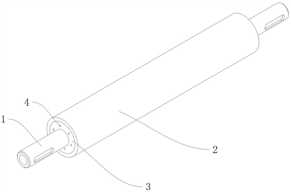
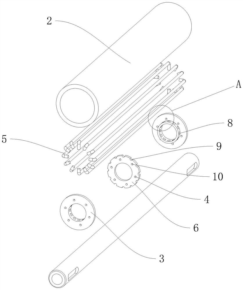
[0040] A textile roller, such as figure 1 , figure 2 and Figure 4 As shown, it includes a roller shaft 1 and a roller body 2, the roller shaft 1 is sleeved with an end sheet 3 positioned at both ends of the roller body 2, and the end sheet 3 is provided with a through hole 4 communicating with the inner chamber of the roller body 2, correspondingly A plurality of support pieces 5 that are attached to the inner wall of the roller body 2 are connected between the adjacent end pieces 3 by clamping.

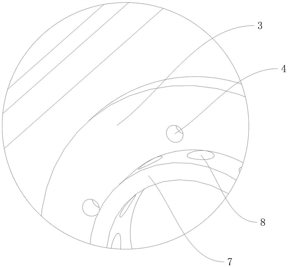
[0041] Such as Figure 2 to Figure 4 As shown, the support member 5 is U-shaped, and the ends of the end pieces 3 facing each other are welded with a circular frustum 7, and the end piece 3 and the circular frustum 7 are in a ring structure, the end piece 3 and the circular frustum 7 are arranged coaxially, and the circular frustum 7 On the outer peripheral wall, there are several slots 8 for accommodating the ends of the supports 5, and the annular arrays of several slots 8 are...

Embodiment 2

[0046] A process for textile rollers, which is used to prepare textile rollers, comprising the following steps: S1, selecting materials, selecting a roller body 2 with a cylindrical structure and a roller shaft 1 with a hollow structure, and detecting whether the outer surfaces of the roller body 2 and the roller shaft 1 are Visible cracks and pits;

[0047] S2, grinding, placing the roller body 2 and the roller shaft 1 on a grinder for grinding, removing the rust on the outer surface of the roller body 2 and the roller shaft 1, and trimming the tolerance of the outer diameter of the roller shaft 1;

[0048] S3, the blanking of the wafer, the steel plate is cut out of the connecting piece 6 in a ring structure by a wire cutting machine, and a number of arc-shaped grooves 9 distributed in a circular array and in a semicircular structure are cut out on the edge of the connecting piece 6, and cut The end piece 3 in the ring structure is produced, the connecting piece 6 and the en...


PUM


Abstract

The invention discloses a spinning roller and a process thereof, and relates to textile accessory processing. The problems that the straightness of an upper roller and a lower roller is influenced andthe cloth conveying efficiency between spinning rollers is influenced due to the fact that deformation occurs under the action of internal heat are solved. According to the key point of the technicalscheme, the spinning roller comprises a roller shaft and a roller body, end pieces located at the two ends of the roller body sleeve the roller shaft, through holes communicating with an inner cavityof the roller body are formed in the end pieces, a plurality of supporting pieces attached to the inner wall of the roller body are detachably connected between the adjacent end pieces, and connecting pieces clamped with the supporting pieces sleeve the middle of the roller shaft. According to the spinning roller, the roller body is reinforced and supported through the supporting pieces, the anti-deformation capacity of the spinning roller is improved, the through holes are formed in the end pieces, air pressure balance between the interior of the spinning roller and the outside is achieved,and deformation caused by heating under the action of internal heat is reduced.

Description

technical field [0001] The invention relates to the processing of textile accessories, more specifically, it relates to a textile roller and its technology. Background technique [0002] Roller is one of the components of textile machinery, widely used in drafting, carding and conveying mechanisms. When the roller is used to draft the yarn, it generally includes an upper roller and a lower roller. The yarn is located between the upper roller and the lower roller. The upper roller exerts pressure on the lower roller to ensure the tension of the yarn. The greater the pressure, the yarn will The greater the tension. [0003] Existing rollers are often sleeved on the roller shaft through the cylinder, and the end piece is welded to the roller shaft by welding at both ends of the cylinder to form a finished roller. According to the situation and occasion of use, people often wrap the roller outside the cylinder. Rubber and other materials increase the friction between the rolle...

Claims


Application Information

Patent Timeline
Patent Type & Authority Applications(China)
IPC IPC(8): B23P15/00B23Q3/06B23Q7/00B23Q11/10
CPCB23P15/00B23Q3/06B23Q7/00B23Q11/10
Inventor 陈祝春
Owner 新昌县顺春机械有限公司
Learn More