Solid-liquid separation device applied to sewage treatment system

A sewage treatment system and solid-liquid separation technology, applied in the direction of filtration separation, separation method, fixed filter element filter, etc., can solve the problems of filter blockage, inability to filter solid impurities in the filter, and affect the efficiency of sewage treatment, etc., to prevent Deposition, good anti-slip effect, anti-clogging effect

Inactive Publication Date: 2021-03-02
广州兴峰达环保新技术有限公司
View PDF1 Cites 5 Cited by
  • Summary
  • Abstract
  • Description
  • Claims
  • Application Information

AI Technical Summary

Problems solved by technology

[0005] Based on the solid-liquid separation device used in the above-mentioned patents, the solid impurities on the filter screen cannot be effectively treated, resulting in the clogging of the filter screen after one end of filtration time, requiring manual replacement and treatment, which affects the treatment efficiency of sewage. Problem, the present invention proposes a solid-liquid separation device applied to sewage treatment systems

Method used


Image

  • Solid-liquid separation device applied to sewage treatment system
  • Solid-liquid separation device applied to sewage treatment system
  • Solid-liquid separation device applied to sewage treatment system

Examples


Embodiment 1

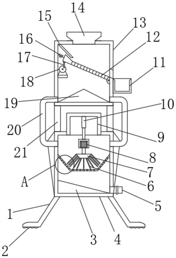
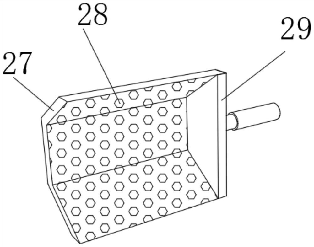
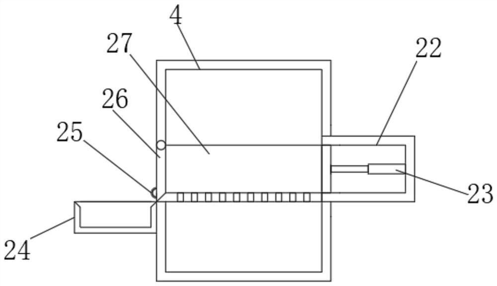
[0029]Refer toFigure 1-4, A solid-liquid separation device applied to a sewage treatment system, comprising a second separation box 4, the two inner walls of the second separation box 4 are fixed with the same filter tank 27 by screws, and the inner wall of the filter tank 27 is provided with filter holes 28. The top outer wall of the second separation box 4 is fixed with a fixed box 9 by screws, and the top inner wall of the fixed box 9 is fixed with an electric telescopic rod 10 by screws, and one end of the piston rod of the electric telescopic rod 10 is fixed with a motor 8 by screws, and The output shaft of the motor 8 is connected with a trapezoidal fixed block 7 through a coupling. The bottom outer wall of the trapezoidal fixed block 7 is provided with five to ten stirring rods 6, and the five to ten stirring rods 6 are arranged in a fan-shaped structure. The second separation box A mounting box 22 is fixed on one side of the outer wall of 4 by screws, and the inner wall of t...

Embodiment 2

[0039]Refer toFigure 5 , A solid-liquid separation device applied to a sewage treatment system. Compared with the first embodiment, this embodiment further includes a hydraulic rod 30 fixed to the bottom outer wall of the second separation box 4 by screws, and one end of the piston rod of the hydraulic rod 30 A fixed suction cup 31 is fixed by screws.

[0040]The piston rod of the control hydraulic rod 30 is extended, and the fixed suction cup 31 can adsorb the ground to fix the device, which improves the stability of the device.


PUM


Abstract

The invention belongs to the technical field of sewage treatment, and particularly relates to a solid-liquid separation device applied to a sewage treatment system. Aiming at the problem that a solid-liquid separation device used in the patent cannot effectively treat solid impurities on a filter screen, so that after filtering is carried out for a period of time, the filter screen is blocked andneeds to be manually replaced, and the sewage treatment efficiency is influenced, the following scheme is provided: the solid-liquid separation device comprises a second separation box, the same filtering groove is fixed to the inner walls of the two sides of the second separation box through screws, filtering holes are formed in the inner wall of the filtering groove, and a fixing box is fixed tothe outer wall of the top of the second separation box through screws. A piston rod of an electric push rod is controlled to extend, a residue pushing plate can push solids into a second waste residue tank to be collected, solid impurities on a filtering tank can be effectively treated, the situation that the filtering tank is blocked after filtering is conducted for a period of time is avoided,and the sewage treatment efficiency is improved.

Description

Technical field[0001]The invention relates to the technical field of sewage treatment, in particular to a solid-liquid separation device applied to a sewage treatment system.Background technique[0002]Sewage treatment is the process of purifying sewage to meet the water quality requirements for discharge into a certain water body or reuse. Sewage treatment is widely used in construction, agriculture, transportation, energy, petrochemical, environmental protection, urban landscape, medical treatment, catering, etc. In the field of sewage treatment, more and more people enter the daily life of ordinary people. In the process of sewage treatment, it is often necessary to carry out solid-liquid separation of sewage.[0003]After searching, the Chinese patent publication number is CN208877981U, which discloses a solid-liquid separation device for sewage treatment, including a separation box. The inner cavity of the separation box is laterally provided with stable sliding rods and positionin...

Claims


Application Information

Patent Timeline
Patent Type & Authority Applications(China)
IPC IPC(8): B01D29/56B01D29/72B01D29/86B01D29/94
CPCB01D29/56B01D29/72B01D29/86B01D29/94
Inventor 林燕璇
Owner 广州兴峰达环保新技术有限公司
Why Eureka
Try Eureka