
Building decoration plate detection device

A detection device and architectural decoration technology, applied in the direction of measuring devices, mechanical devices, and devices for coating liquid on the surface, etc., can solve the problems of low detection efficiency, inability to mark in real time, inconvenient plate rectification, etc., and achieve good detection effect Effect

Inactive Publication Date: 2021-02-26
内江恒威派腾科技有限公司
View PDF0 Cites 1 Cited by
  • Summary
  • Abstract
  • Description
  • Claims
  • Application Information

AI Technical Summary

Problems solved by technology

[0003] In the prior art, the detection of protrusions and depressions on the surface of building decoration boards is mostly carried out by manual hand-held leveling instruments. This detection efficiency is relatively low, and some are automatically detected by mechanical detection equipment, but the existing When mechanical testing equipment detects, it is impossible to mark the parts with protrusions or depressions in real time, which makes it inconvenient for further rectification of subsequent plates

Method used


Image

  • Building decoration plate detection device
  • Building decoration plate detection device
  • Building decoration plate detection device

Examples


Embodiment 1

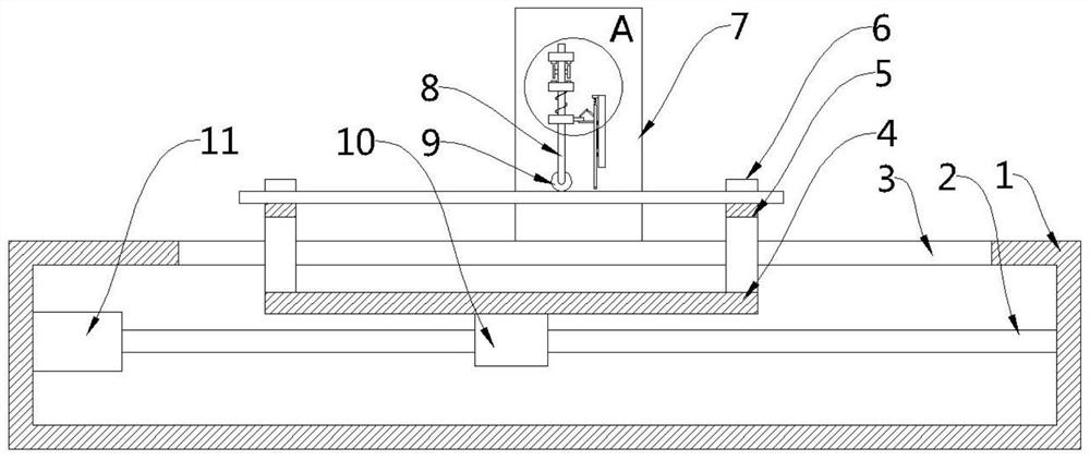
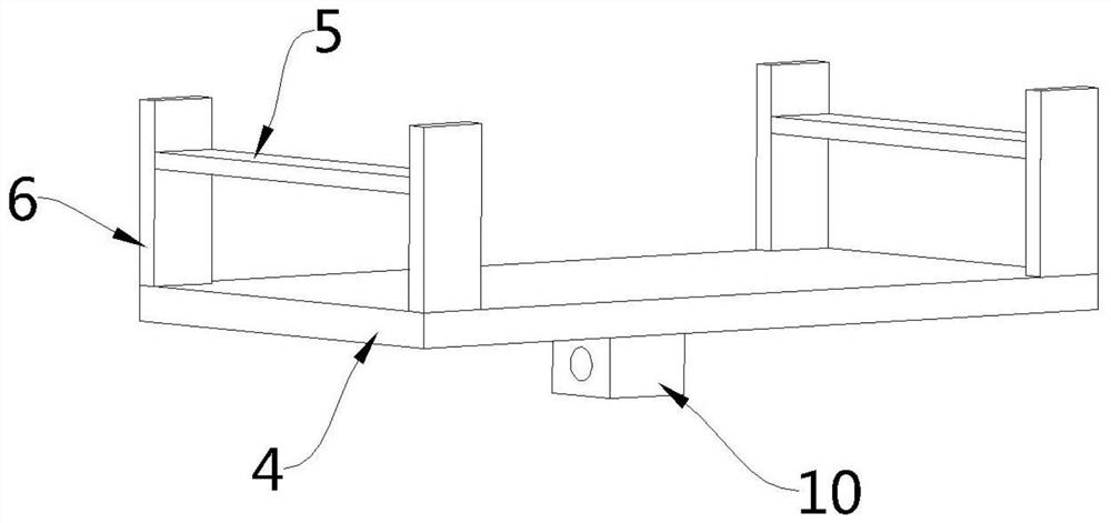
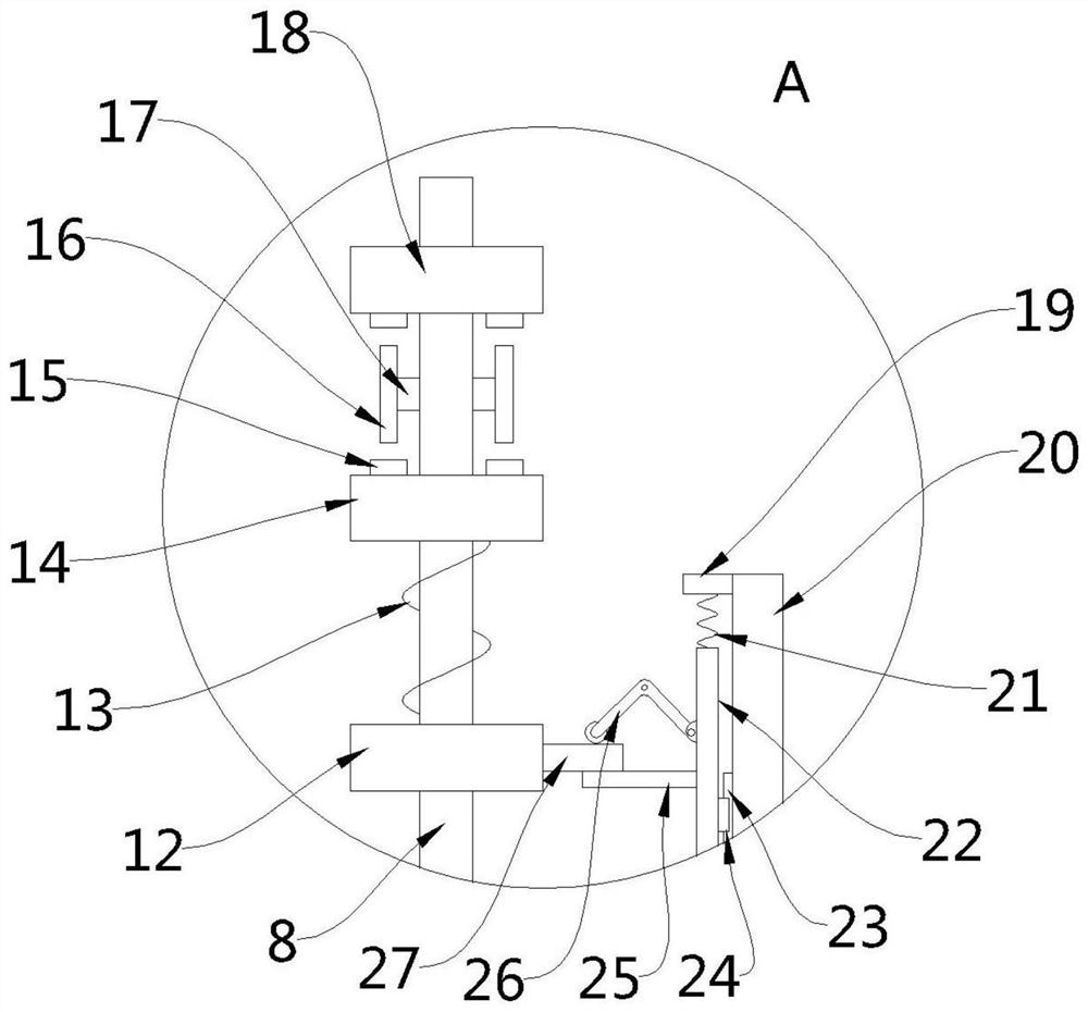
[0026] see Figure 1-3 , the present embodiment provides a detection device for building decoration boards, including a bottom box 1, a support assembly for supporting the board to be tested is arranged on the upper part of the bottom box 1, and a support assembly for driving the support assembly along the bottom is arranged inside the bottom box 1. The drive assembly that moves along the length direction of the box 1, side plates 7 are fixedly installed on the front and rear sides of the upper part of the bottom box 1, and a detection assembly is arranged between the two groups of side plates 7. Specifically, the detection assembly includes two The first guide plate 14 between the set of side plates 7 and the second guide plate 18 fixedly arranged above the first guide plate 14, the vertical penetration between the first guide plate 14 and the second guide plate 18 There is a detection rod 8, and the detection rod 8 is fixedly provided with a fixed block 12 on the rod body be...

Embodiment 2

[0039] see image 3 , a detection device for building decoration boards. Compared with Embodiment 1 in this embodiment, the upper part of the fixed plate 22 facing the detection rod 8 is also fixedly provided with a support 19, and the top of the marking rod 22 is connected to the support. The seats 19 are also connected by the second elastic member 21, through the setting of the second elastic member 21, the marking rod 22 can be reset to ensure that the marking rod 22 is placed above the board when the upper surface of the qualified board is detected. not in contact with the sheet.

[0040] Specifically, the second elastic member 21 is a spring.

[0041] In the embodiment of the present invention, through the setting of the detection rod 8, the elastic member 13, the first guide plate 14, the second guide plate 18, the touch switch 15 and the touch lever 16, the protrusions and depressions on the surface of the plate can be detected , and cooperate with the up and down mov...


PUM


Abstract

The invention provides a building decoration plate detection device, which belongs to the technical field of building decoration plate detection, and comprises a bottom box; wherein the upper part ofthe bottom box is provided with a supporting assembly for supporting a plate to be detected, and the bottom box is internally provided with a driving assembly for driving the supporting assembly to move along the length direction of the bottom box; side plates are fixedly arranged on the front side and the rear side of the upper portion of the bottom box, and a detection assembly is arranged between the two side plates. In the embodiment of the invention, through the arrangement of the detection rod, the elastic piece, the first guide plate, the second guide plate, the touch pressure switch and the touch pressure rod, bulges and recesses on the surface of a plate can be detected, and the bulge positions and the recess positions can be marked in cooperation with the up-down movement of themarking rod, so that a user can directly know the quality of the plate; therefore, the technical scheme is convenient for subsequent targeted rectification, and has the advantage of good detection effect.

Description

technical field [0001] The invention belongs to the technical field of detection of building decoration boards, in particular to a detection device for building decoration boards. Background technique [0002] At present, after the production of architectural decorative panels is completed, the surface quality needs to be tested to prevent unqualified panels from flowing into the market, thereby affecting the reputation of the company. [0003] In the prior art, the detection of protrusions and depressions on the surface of building decoration boards is mostly carried out by manual hand-held leveling instruments. This detection efficiency is relatively low, and some are automatically detected by mechanical detection equipment, but the existing The mechanical detection equipment cannot mark the parts with protrusions or depressions in real time during detection, which makes it inconvenient for further rectification of subsequent plates. Contents of the invention [0004] I...

Claims


Application Information

Patent Timeline
Patent Type & Authority Applications(China)
IPC IPC(8): G01N19/08B05C1/02B25H7/04
CPCB05C1/027B25H7/04G01N19/08
Inventor 代云芬
Owner 内江恒威派腾科技有限公司
Learn More