
Beam-column joint for prefabricated PEC structure system and preparation method

A technology of prefabricated assembly and beam-column joints, which is applied in the direction of building construction and construction, can solve the problems of environmental protection that do not conform to the prefabricated structure, low recyclability, and labor and material resources, and achieve high efficiency and environmental protection in the construction process. Make up for the reduction of section strength and the effect of saving materials

Pending Publication Date: 2021-02-26
ECONOMIC TECH RES INST OF STATE GRID ANHUI ELECTRIC POWER +2
View PDF0 Cites 2 Cited by
  • Summary
  • Abstract
  • Description
  • Claims
  • Application Information

AI Technical Summary

Problems solved by technology

However, in the beam-column joint area of ​​conventional PEC structures, steel bars need to be bound, concrete is poured after the formwork is supported, and there are wet operations and grout leakage during the concrete pouring process, causing site pollution
The connection method of conventional PEC structure beam-column joints is to reserve holes on the web and pass through high-strength bolts, tie the steel bars, support the formwork, and then pour the concrete. There may be exposed bars and corrosion. The steps are numerous and costly A lot of manpower and material resources, long construction period
After the concrete reaches a certain strength, the recyclability of the formwork removed is not high, resulting in construction waste, which does not conform to the concept of green environmental protection of prefabricated structures

Method used


Image

  • Beam-column joint for prefabricated PEC structure system and preparation method
  • Beam-column joint for prefabricated PEC structure system and preparation method
  • Beam-column joint for prefabricated PEC structure system and preparation method

Examples


Embodiment Construction

[0035] In order to make the purpose, technical solutions and advantages of the embodiments of the present invention clearer, the technical solutions in the embodiments of the present invention will be clearly and completely described below in conjunction with the drawings in the embodiments of the present invention. Obviously, the described embodiments It is a part of embodiments of the present invention, but not all embodiments.

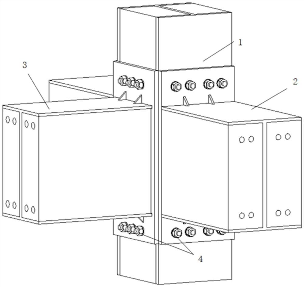
[0036] Such as figure 1 As shown, a new type of prefabricated beam-column joint for PEC system, which includes prefabricated PEC column 1, prefabricated PEC beam 2 with end plate, prefabricated PEC longitudinal beam 3 with end plate, and unilateral bolt 4.

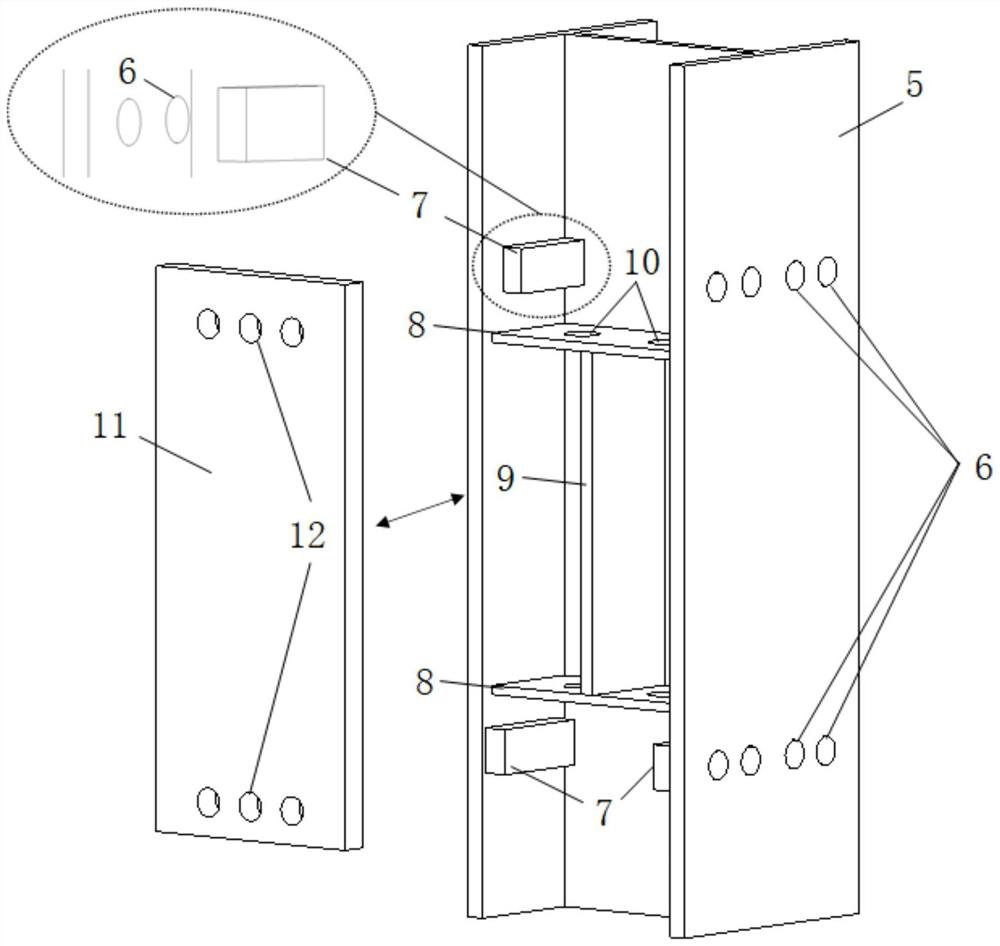
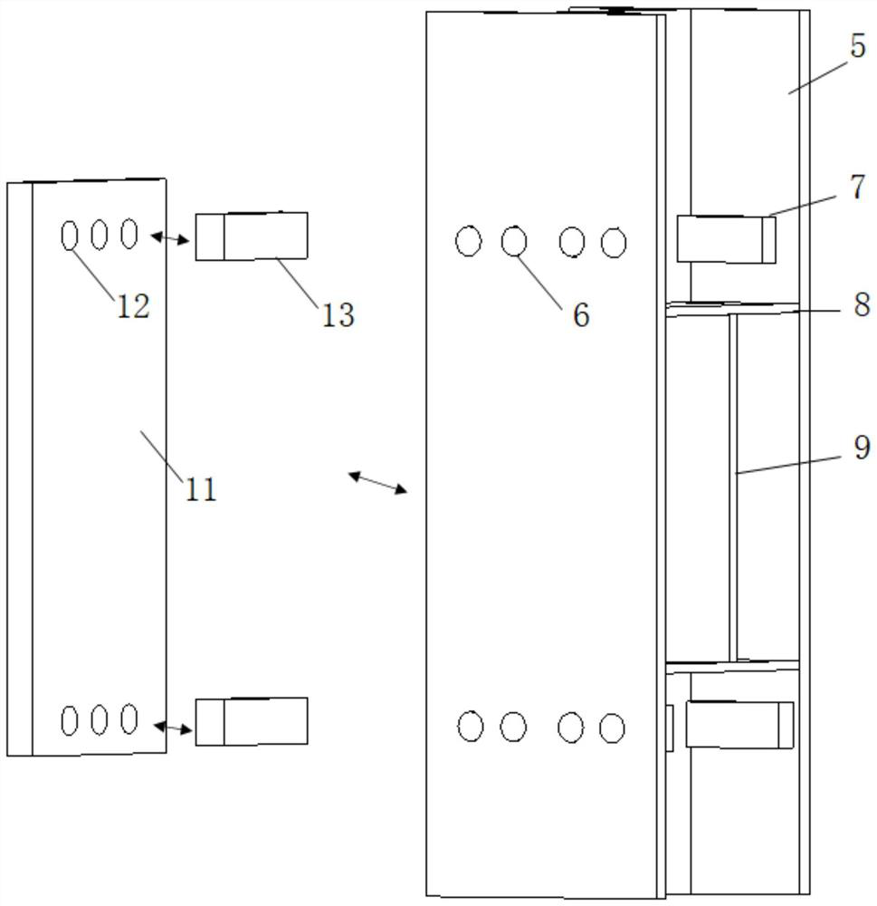
[0037] Such as figure 2 and image 3 As shown, the prefabricated PEC column 1 includes an H-shaped steel concrete column 5, a unilateral bolt hole 6 on the left and right flanges of the H-shaped steel, a channel steel 7 in the H-shaped steel flange, a transverse stiffening plate 8, a longitud...


PUM


Abstract

The invention discloses a beam-column joint for a prefabricated PEC structure system and a preparation method. The beam-column joint comprises a prefabricated PEC column, a prefabricated PEC cross beam with an end plate and a prefabricated PEC longitudinal beam with an end plate. The prefabricated PEC column comprises an H-shaped steel concrete column, single-side bolt hole channels are formed inthe H-shaped steel concrete column, the single-side bolt hole channels are formed in the left flange and the right flange of the H-shaped steel concrete column and are symmetrically arranged left andright relative to a web of the H-shaped steel concrete column, and the single-side bolt hole channels are located on the outer sides of the upper flange and the lower flange of the beam. Channel steelis further arranged on the H-shaped steel concrete column and welded to the inner sides of the left flange and the right flange of the H-shaped steel concrete column, and weld joints are parallel tothe flange direction of the column. The beam-column joint for the prefabricated PEC structure system is simple in structure, convenient to operate, capable of saving materials, low in cost, capable ofachieving direct on-site assembly after a PEC member is prefabricated in a factory, capable of shortening the construction period, easy to install, capable of preventing construction waste from beingformed due to dismantled formworks at the same time, and efficient and environmentally friendly in the construction process.

Description

technical field [0001] The invention relates to the technical field of prefabricated construction engineering, in particular to a beam-column joint used in a prefabricated assembled PEC structure system and a preparation method thereof. Background technique [0002] In recent years, in order to actively respond to the concept of green development, advocate energy-saving and environmentally-friendly construction methods, and achieve sustainable development of the construction industry, the state has intensively introduced policies for the construction industry from the strategic development level to encourage and vigorously promote prefabricated buildings. [0003] Partially clad steel-concrete composite structure (PEC structure) is a composite structure formed by binding steel bars between H-shaped steel flanges and filling concrete. It has the advantages of high bearing capacity, good ductility, and excellent fire and corrosion resistance. It is used in some high-rise build...

Claims


Application Information

Patent Timeline
IPC IPC(8): E04B1/58E04B1/41E04B1/30
CPCE04B1/5812E04B1/41E04B1/30E04B1/388
Inventor 何宇辰李涛胡晨张慧洁王静峰刘用刘伟
Owner ECONOMIC TECH RES INST OF STATE GRID ANHUI ELECTRIC POWER
Learn More