PLC-based sound wave fish expelling system for power plant coal unloading wharf
A wharf and sound wave technology, which is applied in the field of sound wave fish drive system at the coal unloading wharf of the power plant, can solve the problems such as the decline of the fish drive away effect, and achieve the effect of improving the fish drive effect
- Summary
- Abstract
- Description
- Claims
- Application Information
AI Technical Summary
Problems solved by technology
Method used
Image

Examples
Embodiment 1
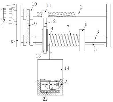
[0024] Example 1 as figure 1 As shown, this PLC-based power plant coal unloading wharf acoustic wave fish driving system includes a first motor 1 and two support plates 8, and is characterized in that the first motor 1 is fixedly arranged on the left side wall of the left support plate 8, And the first motor 1 adopts a stepping motor, which is convenient to realize the positive and negative rotation of the reciprocating screw mandrel 2, and the reciprocating screw mandrel 2 and the first rotating rod 3 are arranged between the two support plates 8, and the reciprocating screw mandrel 2 and the first rotating rod The rod walls at both ends of 3 are rotationally connected with the side walls of the corresponding support plate 8 through the first bearing respectively, the left end of the reciprocating screw rod 2 runs through the left support plate 8 and is fixedly connected with the output end of the first motor 1, and the reciprocating screw rod 2 2 and the first rotating rod 3...
Embodiment 2
[0025] Embodiment 2 is on the basis of embodiment 1 such as figure 1 As shown, its transmission mechanism includes two belts 9 and two pulleys 10, and the two pulleys 10 are fixedly sleeved with the left end rod wall of the reciprocating screw rod 2 and the first rotating rod 3 respectively, and the belt is passed between the two pulleys 10. 9. The transmission connection facilitates the synchronous rotation of the reciprocating screw mandrel 2 and the first rotating rod 3.
Embodiment 3
[0026] Embodiment 3 is on the basis of embodiment 1 such as figure 1 As shown, its connection mechanism includes a reciprocating slider 11, a first connecting rod 12 and a second annular plate 13, the second annular plate 13 is rotationally connected with the first annular plate 6 on the left side through a second bearing, and the first connecting rod 12 is fixedly arranged on the upper surface of the second annular plate 13, the upper end of the first connecting rod 12 is fixedly connected with the reciprocating slider 11, and the reciprocating slider 11 is screwed with the reciprocating screw rod 2.
PUM
 Abstract
Description
Claims
Application Information
 - R&D
- Intellectual Property
- Life Sciences
- Materials
- Tech Scout
- Unparalleled Data Quality
- Higher Quality Content
- 60% Fewer Hallucinations
Browse by: Latest US Patents, China's latest patents, Technical Efficacy Thesaurus, Application Domain, Technology Topic, Popular Technical Reports.
© 2025 PatSnap. All rights reserved.Legal|Privacy policy|Modern Slavery Act Transparency Statement|Sitemap|About US| Contact US: help@patsnap.com