Low-interference unit of base station antenna
A base station antenna, low-interference technology, applied in the direction of antenna, antenna coupling, antenna components, etc., can solve the problems of reducing the size of the antenna, large mutual interference between high and low frequencies, and reducing the emission of high-frequency signals, so as to reduce the size of the antenna and reduce the occupation. space, the effect of reducing the volume
- Summary
- Abstract
- Description
- Claims
- Application Information
AI Technical Summary
Problems solved by technology
Method used
Image

Examples
Embodiment 1
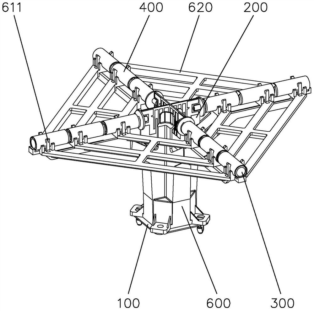
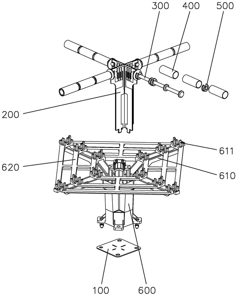
[0023] Embodiment 1, with reference to figure 2 , the base 100 is fixed on the upper side of the reflector. There are two microstrip supporting PCBs 200 , specifically, the two microstrip supporting PCBs 200 are spliced into a cross shape. There are four dipole arms 300 , facing the front side, the left side, the back side and the right side of the antenna unit respectively. Full-wave dipoles are distributed on the vibrator arm 300 .
Embodiment 2
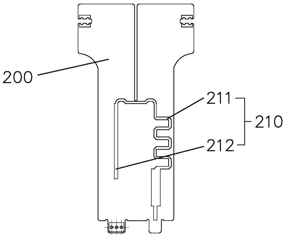
[0024] Embodiment 2, Microstrip Support The "microstrip" of the PCB 200 refers to the conductive strip separated from the ground plane by the dielectric layer on the printed circuit board. refer to image 3 , the front of the microstrip support PCB200 is provided with a feed coupling line conversion circuit 210, referring to Figure 4 , the back of the microstrip support PCB 200 is provided with a feed circuit 220 , and the height of the feed coupling line conversion circuit 210 is less than 1 / 2 of the distance between the vibrator arm 300 and the base 100 . Both the feed coupling line conversion circuit 210 and the feed circuit 220 are microstrip circuits. The height adjustment of the feeding coupling line conversion circuit 210 can reduce the reflection and coupling of high-frequency signals, and suppress the high-frequency induced current on the feeding sheet.
[0025] In this embodiment, optionally, the feed coupling line conversion circuit 210 includes a microstrip balu...
Embodiment 3
[0026] Embodiment 3, with reference to figure 2 , A sleeve fixing ring 500 is disposed between the choke sleeve 400 and the vibrator arm 300 . The sleeve fixing ring 500 is set on the vibrator arm 300, and then the choke sleeve 400 is set on the sleeve fixing ring 500, so as to realize the fixing of the choke sleeve 400 and ensure the connection between the choke sleeve 400 and the vibrator arm 300. There is no direct contact, and there is enough space between the choke sleeve 400 and the dipole arm 300 to ensure the normal operation of the antenna.
[0027] In this embodiment, optionally, the vibrator arm 300 is a column structure.
[0028] In this embodiment, optionally, the sleeve fixing ring 500 is a C-shaped ring. Optionally, the sleeve fixing ring 500 is embedded with PTFE medium. Optionally, the value range of the ratio of the outer diameter of the vibrator arm 300 to the inner diameter of the choke sleeve 400 is Optionally, the ratio of the outer diameter of the ...
PUM
 Abstract
Description
Claims
Application Information
 - R&D
- Intellectual Property
- Life Sciences
- Materials
- Tech Scout
- Unparalleled Data Quality
- Higher Quality Content
- 60% Fewer Hallucinations
Browse by: Latest US Patents, China's latest patents, Technical Efficacy Thesaurus, Application Domain, Technology Topic, Popular Technical Reports.
© 2025 PatSnap. All rights reserved.Legal|Privacy policy|Modern Slavery Act Transparency Statement|Sitemap|About US| Contact US: help@patsnap.com