Hydraulic oil cylinder with buffering and flow limiting capacity

A technology of hydraulic cylinder and current limiting capacity, which is applied in the field of hydraulic cylinder, which can solve the problem of easy damage of the end of the cylinder, and achieve the effect of increasing the magnetic field strength, increasing the service life, and strengthening the buffering capacity

Pending Publication Date: 2021-02-23
朱珊珊
View PDF0 Cites 1 Cited by
  • Summary
  • Abstract
  • Description
  • Claims
  • Application Information

AI Technical Summary

Problems solved by technology

[0004] The purpose of the present invention is to solve the problem that the end of the oil cylinder is easily damaged in the prior art, and propose a hydraulic oil cylinder with buffering and flow limiting capacity

Method used


Image

  • Hydraulic oil cylinder with buffering and flow limiting capacity
  • Hydraulic oil cylinder with buffering and flow limiting capacity

Examples


Embodiment

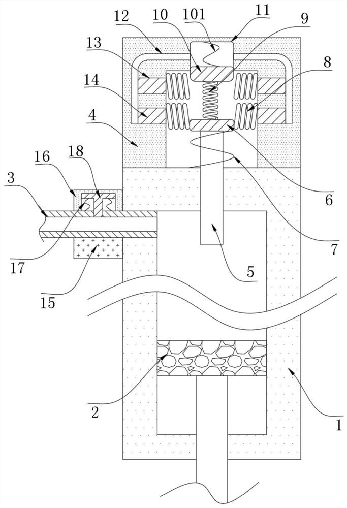
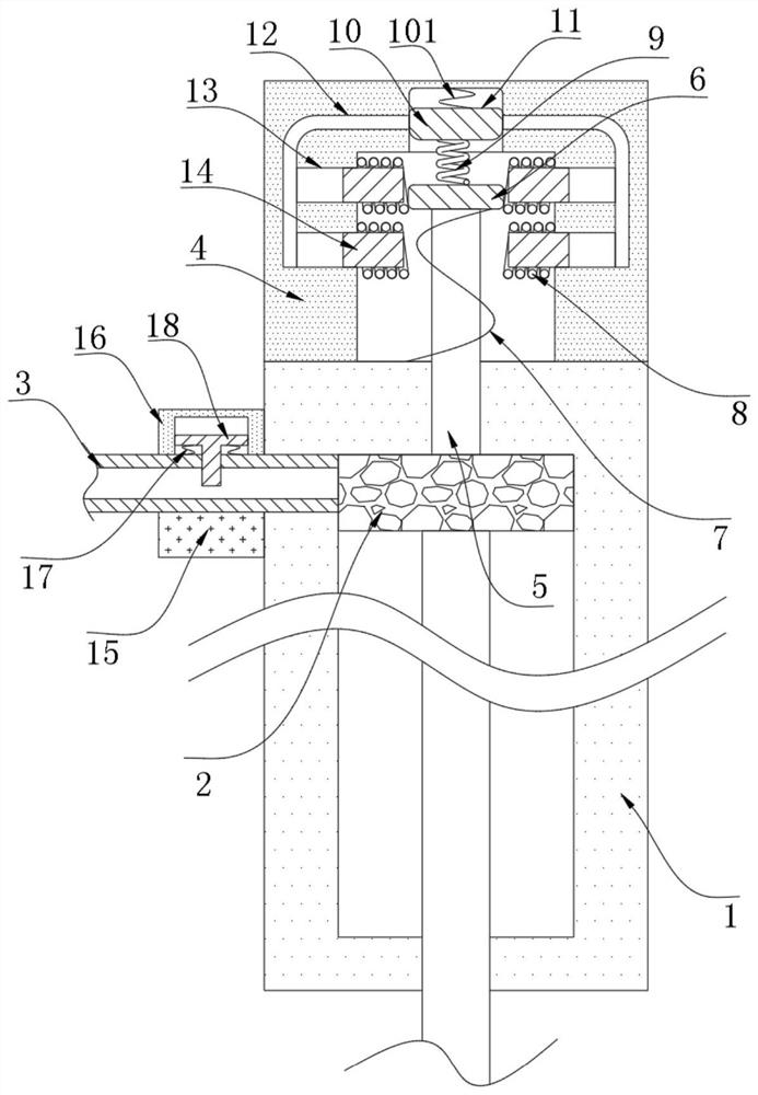
[0019] refer to Figure 1-2 , a hydraulic oil cylinder with buffering and current limiting capability, comprising a cylinder body 1, the inner wall of the cylinder body 1 is sealed and slidably connected with a piston rod 2, the side wall of the cylinder body 1 is penetrated and fixed with an oil pipe 3, and the side wall of the cylinder body is fixed There is a buffer box 4, and the side wall of the cylinder body 1 is inserted with a buffer rod 5 extending to the inside of the buffer box 4. The buffer rod 5 and the cylinder body 1 seal and slide without causing oil leakage, and the inner wall of the buffer box 4 passes through The buffer spring 7 is connected with a force plate 6, the force plate 6 is fixed to the buffer rod 5, and the inner wall of the buffer box 4 is fixed with multiple groups of coils 8, and the coils 8 are arranged correspondingly to form a stable magnetic field. Strengthen institutions.

[0020] The electromagnetic strengthening mechanism includes a pre...


PUM


Abstract

The invention discloses a hydraulic oil cylinder with the buffering and flow limiting capacity. The hydraulic oil cylinder comprises a cylinder block, a piston rod is connected to the inner wall of the cylinder block in a sealed and sliding mode, an oil pipe is fixed to the side wall of the cylinder block in a penetrating mode, a buffering box is fixed to the side wall of the cylinder block, and abuffering rod extending into the buffering box is inserted into the side wall of the cylinder block in a penetrating mode. The inner wall of the buffering box is connected with a stress plate througha buffering spring, the stress plate is fixed to the buffering rod, and a plurality of sets of coils are fixed to the inner wall of the buffering box. The hydraulic oil cylinder has the advantages that by arranging the buffering spring, when the piston rod contracts quickly, the impact capacity can be converted into elastic potential energy to be stored by the buffering spring, so that the directimpact force of the piston rod is relieved, the cylinder block cannot be damaged due to strong impact of the piston rod, and the effective service life of the cylinder block is prolonged.

Description

technical field [0001] The invention relates to the technical field of oil cylinders, in particular to a hydraulic oil cylinder with buffering and current limiting capabilities. Background technique [0002] The hydraulic cylinder is the actuator in the hydraulic transmission system. It is an energy conversion device that converts hydraulic energy into mechanical energy, and is used to drive the working mechanism to perform linear reciprocating motion or reciprocating swing. A hydraulic cylinder generally includes a cylinder barrel and a piston rod assembly, and the piston rod assembly includes a piston and a piston rod. [0003] In the reciprocating motion of the hydraulic cylinder, the piston and piston rod are the main components that bear the feedback force of the working mechanism, and when the piston rod and piston are stressed, they will also generate impact on the cylinder itself, especially when moving at high speed, the cylinder is very vulnerable However, the cus...

Claims


Application Information

Patent Timeline
Patent Type & Authority Applications(China)
IPC IPC(8): F15B15/14F15B15/20F15B15/22F15B13/02F15B21/08
CPCF15B13/021F15B13/023F15B15/1423F15B15/1447F15B15/149F15B15/202F15B15/22F15B15/226F15B15/227F15B21/087
Inventor 朱珊珊
Owner 朱珊珊
Why Eureka
Try Eureka