
Power cabinet

A power cabinet and main body technology, applied in electrical components, substation/distribution device housing, substation/switch layout details, etc. The effect of high endurance

Pending Publication Date: 2021-02-19
万文情
View PDF1 Cites 0 Cited by
  • Summary
  • Abstract
  • Description
  • Claims
  • Application Information

AI Technical Summary

Problems solved by technology

[0006] In order to solve the technical problems existing in the background technology, the present invention proposes a power cabinet, which solves the problem that it is difficult to dissipate heat in rainy days, and rainwater is easy to intrude and accumulate in the gaps and storage parts, causing damage to the parts of the power box and making it impossible to supply power.

Method used


Image

  • Power cabinet
  • Power cabinet
  • Power cabinet

Examples


Embodiment 1

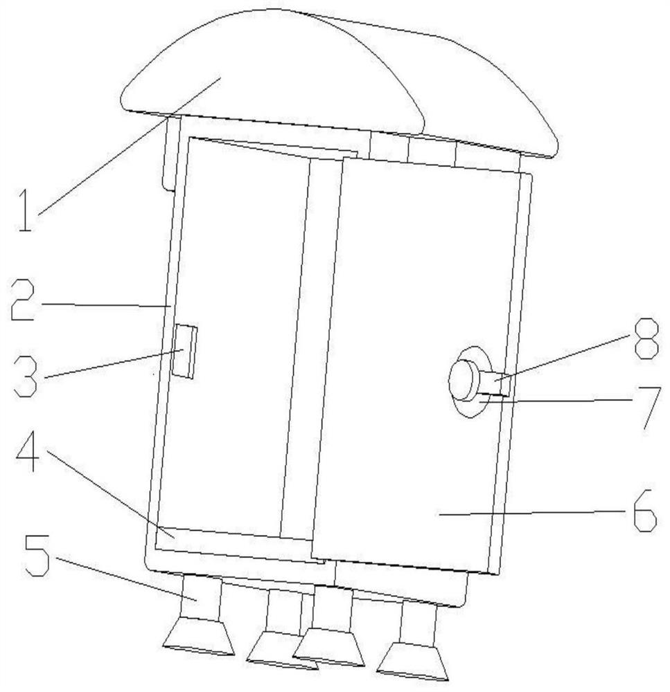
[0035] Such as Figure 1-2 , a technical solution proposed by the present invention: a power cabinet, including a main body 2, the top of the main body 2 is always provided with a blocking device 1, both sides of the bottom of the main body 2 are fixedly connected with support seats 5, and the bottom of the inner cavity of the main body 2 is fixed The adjustment device 4 is connected, the left inner wall of the main body 2 is provided with a card slot 3, the front right side of the main body 2 is connected with a box door 6, the front right side of the box door 6 is always provided with a handle 8, and the front side of the handle 8 is fixedly connected There are card blocks 8.

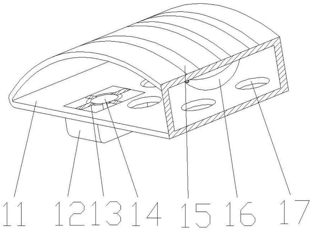
[0036] Wherein, the blocking device 1 includes a casing 11, the top of the casing 11 is provided with a circulation groove 15, the middle position on both sides of the bottom of the casing 11 is fixedly connected with a cooling mechanism 12, and the top of the cooling mechanism 12 is fixedly connected...

Embodiment 2

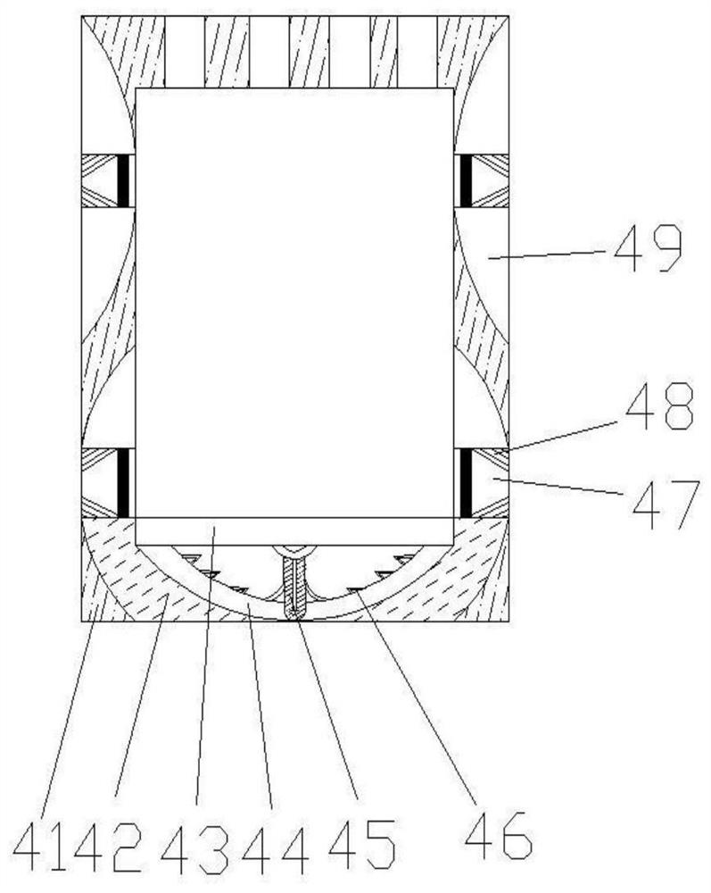
[0039] Such as Figure 1-6 As shown, on the basis of Embodiment 1, the present invention provides a technical solution: the adjustment device 4 includes a frame body 41, the bottom of the frame body 41 is provided with a control mechanism 43, and the middle position of the bottom of the control mechanism 43 is fixedly connected with a fixed rod 45, the bottom end of the fixed rod 45 is fixedly connected with an elastic sheet 44, the inner surface of the elastic sheet 44 is fixedly connected with fixed teeth 46, the bottom two sides of the frame body 41 are fixedly connected with baffle plates 42, and the inner walls of both sides of the frame body 41 are opened There is a regulating port 47 , the inner wall of the regulating port 47 is provided with a regulating fan 48 , and the inner walls of both sides of the frame body 41 are located on both sides of the regulating port 47 and are provided with regulating plates 49 .

[0040] When in use, fix the power cabinet, close the bo...

Embodiment 3

[0042] Such as Figure 1-6 As shown, on the basis of Embodiment 1 and Embodiment 2, the present invention provides a technical solution: the heat dissipation mechanism 12 includes a box body 121, and the bottom of the inner cavity of the box body 121 is provided with a cooling hole 125, and the inner cavity of the box body 121 A storage box 122 is fixedly connected to the left side of the bottom, a placement groove 123 is provided at the bottom of the right side of the storage box 122 , and a stopper 124 is provided at the middle of the inner walls of both sides of the placement groove 123 .

[0043] Wherein, the arc-shaped block 16 includes a resilient piece 162, the left top of the resilient piece 162 is provided with a turning arc 161, the middle position of the top of the resilient piece 162 is fixedly connected with a frame 164, and the top of the resilient piece 162 is provided with an upper swing plate 163. An outer pushing block 165 is fixedly connected to the middle p...


PUM


Abstract

The invention discloses a power cabinet which comprises a main body, a blocking device is always arranged at the top of the main body, supporting bases are fixedly connected to the two sides of the bottom of the main body, an adjusting device is fixedly connected to the bottom of an inner cavity of the main body, a clamping groove is formed in the inner wall of the left side of the main body, anda box door is rotatably connected to the right side of the front face of the main body; and a handle is arranged in the middle of the right side of the front face of the box door all the time, and a clamping block is fixedly connected to the front face of the handle. The invention relates to the technical field of power equipment. According to the waterproof power cabinet, blocking can be performed in rainy days, rainwater does not easily stay, the adjusting device can be finely adjusted in the main body, so that heat dissipation is facilitated in rainy days, the situation that rainwater invades and accumulates in gaps and storage parts, and power cannot be supplied due to damage of power box parts is avoided, and rainwater circulation in rainy days is relatively convenient due to the circulation groove; through the arrangement of the through holes, the internal temperature is convenient to circulate, the heat dissipation speed is increased through the work of the heat dissipation fan,and the blowing range is increased.

Description

technical field [0001] The invention relates to the technical field of electric equipment, in particular to an electric cabinet. Background technique [0002] In order to facilitate the control and maintenance of power, the power control switch is generally installed in the power cabinet. The general power cabinets are installed outdoors, and most of them are installed on the ground. During heavy rain, rainwater easily enters the inside of the power cabinet. , The power cabinet at a high place is inconvenient to detect and maintain, which not only affects the detection and maintenance efficiency of the power cabinet, but also is prone to invisible accidents when the staff is climbing. The power cabinet on the ground is easy to be eroded or submerged by rainwater on the ground At the bottom, the power cabinet is prone to water ingress and damp. [0003] According to a rainy weather waterproof power cabinet disclosed in Chinese Patent No. CN107634452A, the circular through ho...

Claims


Application Information

Patent Timeline
IPC IPC(8): H02B1/30H02B1/46H02B1/28H02B1/56
CPCH02B1/28H02B1/30H02B1/306H02B1/46H02B1/565
Inventor 万文情
Owner 万文情
Learn More