
OTDR-based optical cable test active alarm method

An optical cable, active technology, applied in the field of optical network communication, can solve the problems of reduced communication quality, only display distance, insufficient accuracy of optical cable fault location, etc.

Active Publication Date: 2021-02-19
NO 34 RES INST OF CHINA ELECTRONICS TECH GRP
View PDF7 Cites 7 Cited by
  • Summary
  • Abstract
  • Description
  • Claims
  • Application Information

AI Technical Summary

Problems solved by technology

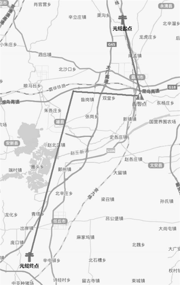
[0004] With the continuous expansion of the network scale and the continuous improvement of communication quality requirements, the traditional optical cable monitoring technology has exposed many defects, such as: the accuracy of optical cable fault location is insufficient: due to technical reasons, the traditional optical cable monitoring equipment has a large error in fault location and reports If it is not timely, the traditional software can only display the distance, but cannot locate the latitude and longitude. When a fault occurs, the maintenance personnel can only check point by point along the optical cable line, which consumes a lot of manpower and material resources and reduces the communication quality; traditional optical cable monitoring software The logical circuit diagram can be displayed on the map, but the fault point cannot be displayed on the map, or the latitude and longitude of the fault point cannot be accurately obtained, so that it cannot be displayed on the map in real time and effectively when a fault occurs; in traditional network communication, when the optical cable fails , when the maintenance personnel complete the repair, the maintenance information is recorded or there is no record, lack of information management of optical cable maintenance information, and lack of long-term consideration of the maintenance of optical cable lines

Method used


Image

  • OTDR-based optical cable test active alarm method
  • OTDR-based optical cable test active alarm method
  • OTDR-based optical cable test active alarm method

Examples


Embodiment

[0067] A kind of active warning method of optical cable test based on OTDR, comprises the steps:

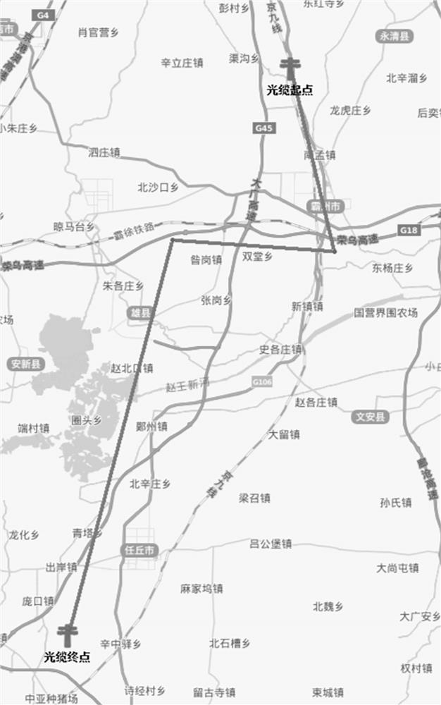
[0068] 1) Display the logical information of the optical cable on the map according to the physical optical cable information: including:

[0069] 1-1) Establish the optical cable information data table: the optical cable information data table includes Table 1, namely the optical_cable table, and Table 2, the optical_cable_passpoint table, wherein Table 1 includes the name of the optical cable, the length of the optical cable, the distance of the optical cable, the number of optical fibers, the name of the affiliated unit, and the creation time And modification time information, Table 2 includes the name of the optical cable corresponding to the name of the optical cable in Table 1, the serial number of the passing point, the type of the passing point, the latitude and longitude of the passing point, Table 1 and Table 2 are as follows respectively:

[0070] Table 1: Each data it...


PUM


Abstract

The invention discloses an OTDR-based optical cable test active alarm method, which is characterized by comprising the following steps of 1) displaying optical cable logic information on a map according to physical optical cable information; 2) establishing a corresponding relation data table of test equipment and optical cable data; 3) testing an optical cable; Fault points can be visually and accurately positioned on a map by using a geographic information system (GIS), and optical cable line maintenance information is recorded through an informatization method, so that maintenance personnelcan conveniently and effectively maintain the optical cable for a long time, a loss function per kilometer of the optical cable is provided, and optical cable lines which possibly have faults are found in advance; operation and maintenance cost of the communication network is reduced, operation and maintenance efficiency is improved, and network communication quality is improved.

Description

technical field [0001] The invention relates to the field of optical network communication, in particular to an OTDR-based active alarm method for optical cable testing. Background technique [0002] Optical network communication is a communication method in which light waves are used as information carriers and optical fibers are used as transmission media. Since Gao Kun proposed the concept of optical fiber communication in 1966, optical network communication has been widely studied by many scholars and widely used in real life, and has become the main pillar of modern communication. [0003] In the optical transmission network, communication line fault location technology is the core pillar of communication network fault repair. Fast and accurate positioning technology can greatly improve the efficiency of communication line fault repair, and the early warning function of optical cable loss can effectively reduce communication network faults and improve network quality. ...

Claims


Application Information

Patent Timeline
Patent Type & Authority Applications(China)
IPC IPC(8): G06F16/242G06F16/22G06F16/28G06F16/29H04B10/079
CPCG06F16/2433G06F16/284G06F16/2282H04B10/0795H04B10/079G06F16/29
Inventor 嵇凌钟伟韦国富查显伟李肖克王国法胡芳芳黄弼胜周伟娟秦润发黄子君
Owner NO 34 RES INST OF CHINA ELECTRONICS TECH GRP
Learn More