Electrical automation instrument protection device
An electrical automation and protection device technology, applied in measuring devices, instruments, liquid/fluid solid measurement, etc., can solve problems such as affecting the use of instruments, lack of instrument protection measures, surface corrosion of flow measuring instruments, etc., to improve the accuracy of indications durability and service life, easy installation of the box, and the effect of damping the flow meter
- Summary
- Abstract
- Description
- Claims
- Application Information
AI Technical Summary
Problems solved by technology
Method used
Image
Examples
Embodiment 1
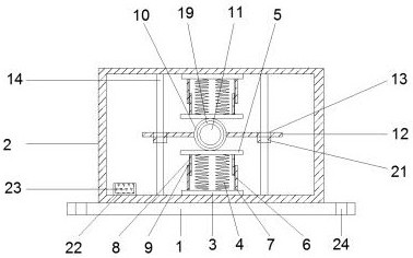
[0030] Example 1 see figure 1 and Figure 5 , according to an embodiment of the present invention, an electrical automation instrument protection device includes a support plate 1, a box body 2 is fixed on the support plate 1, a shock absorber is fixed symmetrically on the upper and lower inner walls of the box body 2, and the shock absorber includes The first fixed plate 3, the first spring 4 and the second fixed plate 5, the first fixed plate 3 is all installed on the upper and lower inner walls of the casing, and the first fixed plate 3 is fixedly provided with a quantity of two on one side away from the inner wall of the casing 2 The first spring 4, the first spring 4 is fixed with the second fixed plate 5 at one side away from the first fixed plate 3, and the first semi-annular plate 6 is fixed at both ends of the first fixed plate 3, the first semi-annular The inner wall of the plate 6 is fixed with a first damping sheet 7, the two ends of the second fixed plate 5 are f...
Embodiment 2
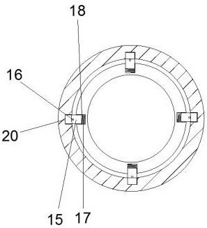
[0032] Embodiment 2 Please refer to on the basis of embodiment 1 Figure 3-4 , for the connection assembly, the connection assembly includes an annular plate 19, a fixed block 15, a connecting rod 16, a second spring 17 and a first groove 18, the annular plate 19 is fixedly sleeved on the outer wall of the flow meter 11, and the outer wall of the annular plate 19 is opened There are four first grooves 18, the inner wall of the ring protection frame 10 is provided with four second grooves 20 matching the first grooves 18, and the bottom of the first groove 18 is fixed with a second groove. The spring 17 and the top of the second spring 17 are fixed with a fixed block 15 .
[0033] Through the above solution of the present invention, the flow meter 11 can be fixedly connected with the annular protection frame 10, and the movement of the fixed block 15 can be restricted.
Embodiment 3
[0034] Embodiment 3 Please refer to on the basis of embodiment 1 Figure 1-2 , for the chute, the outer wall of one side of the fixed block 15 is fixedly provided with a connecting rod 16 , one side of the first groove 18 is provided with a chute 25 , and the connecting rod 16 runs through the chute 25 .
[0035] Through the above solution of the present invention, disassembly can be facilitated.
PUM
 Abstract
Description
Claims
Application Information
 - Generate Ideas
- Intellectual Property
- Life Sciences
- Materials
- Tech Scout
- Unparalleled Data Quality
- Higher Quality Content
- 60% Fewer Hallucinations
Browse by: Latest US Patents, China's latest patents, Technical Efficacy Thesaurus, Application Domain, Technology Topic, Popular Technical Reports.
© 2025 PatSnap. All rights reserved.Legal|Privacy policy|Modern Slavery Act Transparency Statement|Sitemap|About US| Contact US: help@patsnap.com


