Sealing structure of irrigation and drainage device for aquaculture

A sealing structure and aquaculture technology, applied to pump devices, parts of pumping devices for elastic fluids, non-variable pumps, etc., can solve the problem of losing the sealing effect of the sealing surface, reducing the service life and working efficiency of centrifugal pumps , vibration and other issues, to achieve the effect of improving the mechanical sealing effect, reducing the probability of thermal deformation, and increasing the contact area

Pending Publication Date: 2021-02-19
蒋秀玉
View PDF0 Cites 1 Cited by
  • Summary
  • Abstract
  • Description
  • Claims
  • Application Information

AI Technical Summary

Problems solved by technology

[0003] 1. The existing mechanical seal device installs a spring between the moving ring seat and the fixed plate to transmit the pressure on one side of the moving ring from the conveyed liquid, so that the moving ring and the static ring fit closely, and through the spring To buffer the axial force of the centrifugal pump and improve the stability of the pump, but the use of springs to transmit this force will be limited by the length of the spring itself, which greatly shortens the distance for buffering the axial force. This distance is only between each adjacent coil of the spring. The distance between the gaps and the spring's rebound force are relatively large. Although it can buffer part of the axial force, the restoring force after the buffer will cause the pump to vibrate in the opposite direction, so that the shaft of the pump cannot be well buffered. At the same time, in the long-term working environment with the rotation of the pump shaft, it will not only cause relative rotation between the spring and the moving ring seat, causing the spring to scratch the moving ring seat and reduce the service life of the product. At the same time, due to high-speed rotation The pump shaft of the pump will make the spring irreversibly twisted, so that the spring cannot be restored after a long time of use, resulting in the failure of the spring, and the spring is always in contact with the liquid being conveyed, which accelerates the corrosion of the spring and reduces the spring. The service life of the pump is reduced, and the service life of the pump is reduced, more frequent maintenance is required, and the cost of use is increased.
[0004] 2. In the existing mechanical seal, the moving ring and the static ring match each other, and the two sealing surfaces are closely matched with each other, so that a small gap is formed between the sealing end faces, and a very thin liquid film is formed in it by conveying fluid, so that The sealing surfaces can rotate relative to each other, but the existing sealing surfaces are a flat surface, and since the sealing surfaces need to be in close contact, heat will be generated through friction during the rotation process, and with the heat The increase of the height will cause thermal deformation of the sealing surface, which will cause the sealing surfaces to be unable to fit completely. Once a little deformation occurs between the sealing surfaces, the entire sealing surface will lose its sealing effect, especially in aquaculture. Because there are many sundries in the breeding pool, once the sundries enter between the sealing end faces, the high-speed relative rotation between the pressure extrusion memory dynamic and static rings will easily wear the sealing end faces, resulting in leakage of the centrifugal pump. phenomenon, thereby reducing the service life and working efficiency of the centrifugal pump

Method used


Image

  • Sealing structure of irrigation and drainage device for aquaculture
  • Sealing structure of irrigation and drainage device for aquaculture
  • Sealing structure of irrigation and drainage device for aquaculture

Examples


Embodiment Construction

[0021] The following will clearly and completely describe the technical solutions in the embodiments of the present invention with reference to the accompanying drawings in the embodiments of the present invention. Obviously, the described embodiments are only some, not all, embodiments of the present invention. Based on the embodiments of the present invention, all other embodiments obtained by persons of ordinary skill in the art without making creative efforts belong to the protection scope of the present invention.

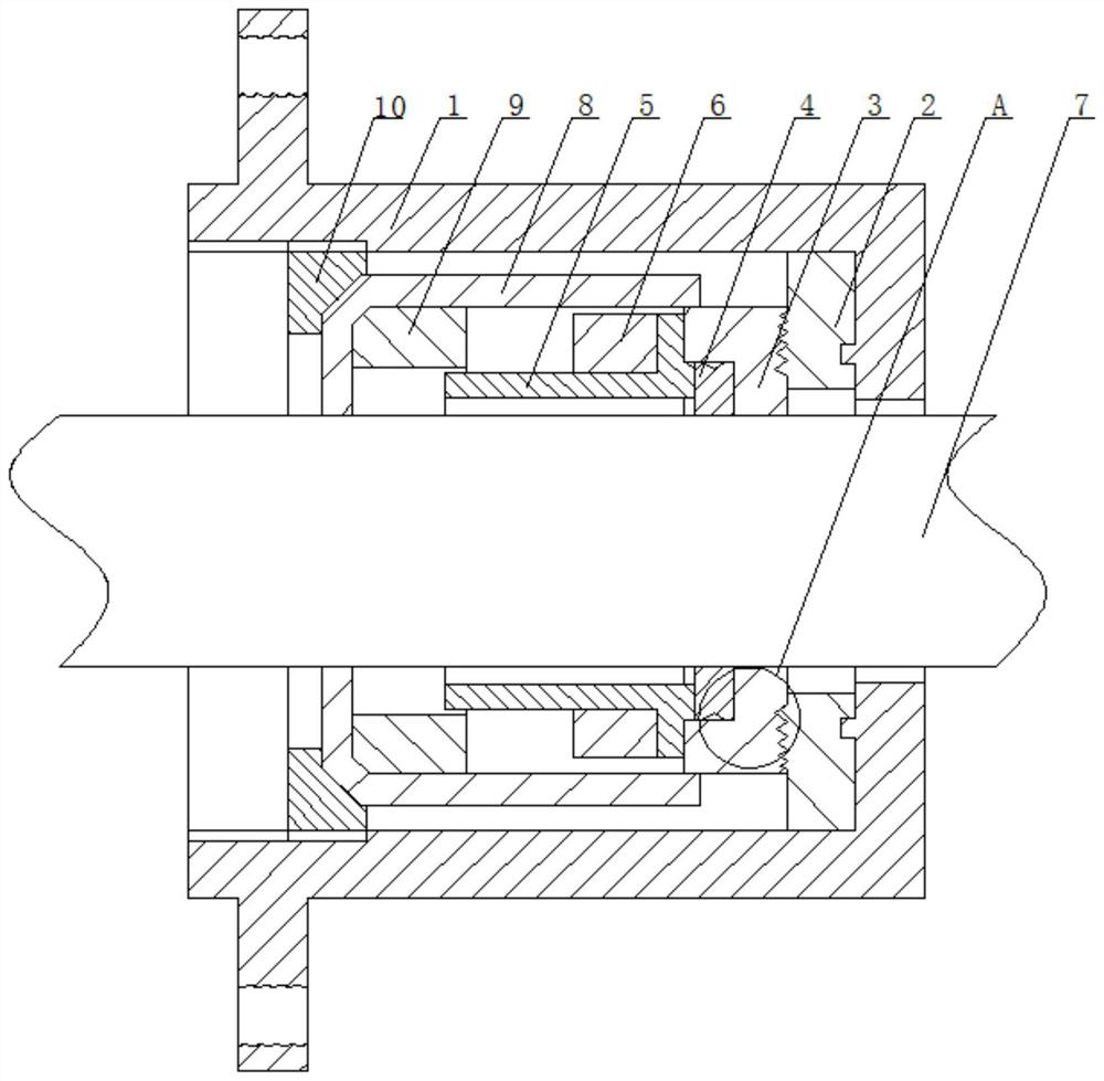
[0022] see Figure 1-5 As shown in one of the present invention, a sealing structure of irrigation and drainage device for aquaculture according to the present invention is fixed on the output end of the centrifugal pump, which includes a casing 1, and a pump shaft 7 runs through the central axis of the casing 1, and the output The end is rotatably connected with the top cover of the housing 1 through a bearing. The inner side of the top cover of the housing 1...


PUM


Abstract

The invention discloses a sealing structure of an irrigation and drainage device for aquaculture. The sealing structure comprises a shell, annular magnets with the same polarity are installed betweena movable ring base and a fixed piece, and a buffer space is formed between the movable ring base and the fixed piece through repulsive force by means of the principle that like poles repel each other. Due to the fact that repulsive force between the magnets can have a better buffering effect compared with elastic force of a spring, buffering is made smoother, and the space between the movable ring base and the fixed piece can ensure that under the action of the magnetic repulsive force, the pressure between a movable ring and a static ring is not too large through movement of the movable ringbase and the fixed piece in the space. On one hand, friction between the movable ring and the static ring is reduced, generated heat is reduced, and the working stability of the movable ring and thestatic ring is guaranteed; and on the other hand, the influence of liquid on the magnets in use is small, and the service life of a centrifugal pump is prolonged.

Description

technical field [0001] The invention relates to the technical field of centrifugal pumps, in particular to a sealing structure for irrigation and drainage devices for aquaculture. Background technique [0002] In aquaculture, the sealing structure of the drainage and irrigation device is mainly a water pump, which uses the water pump to inject water and drain water into the pool, to ensure the different water level requirements of the aquatic organisms in the pool at each growth stage and to increase the comprehensive production conditions of the pool water, and improve the primary level of the pool water. Productivity, so that aquatic organisms have a suitable living environment, in which centrifugal pumps are widely used in this production, and mechanical seals are very important sealing devices in centrifugal pumps. It is a shaft sealing device for rotating machinery. And with the cooperation of the auxiliary seal, it is a device to prevent fluid leakage by keeping fit an...

Claims


Application Information

Patent Timeline
Patent Type & Authority Applications(China)
IPC IPC(8): F04D29/12F04D13/06F04D29/58
CPCF04D13/06F04D29/126F04D29/586
Inventor 蒋秀玉
Owner 蒋秀玉
Why Eureka
Try Eureka