
Safety device for tunnel deceleration

A safety device and tunnel technology, applied in measuring devices, cleaning methods using gas flow, roads, etc., can solve problems such as easy occurrence of traffic accidents, damage to speed bumps, and delay in taking them, so as to improve accuracy, service life, and service life. , improve the effect of security

Inactive Publication Date: 2021-02-19
瑞安斌团电子科技有限公司
View PDF0 Cites 1 Cited by
  • Summary
  • Abstract
  • Description
  • Claims
  • Application Information

AI Technical Summary

Problems solved by technology

[0002] Tunnel is an engineering building buried in the ground, and it is a form of human use of underground space. The speed of vehicles driving in tunnels is often higher than the speed of vehicles on ordinary roads, so it is easy to cause car accidents due to excessive speed, especially just When entering the tunnel, due to the sudden dimming of the light, the driver will not be able to see the road ahead clearly, so it is too late to take measures, which is prone to car accidents; if the traditional speed reduction belt is laid, although it will achieve a certain speed reduction, it will affect the normal driving People's mentality is prone to road rage, which affects the driving psychology of driving after entering the tunnel, and is prone to car accidents, thereby reducing the driver's life safety. damage, thereby increasing the cost of maintenance, a safety device for tunnel deceleration set forth in the present invention can solve the above problems

Method used


Image

  • Safety device for tunnel deceleration
  • Safety device for tunnel deceleration
  • Safety device for tunnel deceleration

Examples


Embodiment Construction

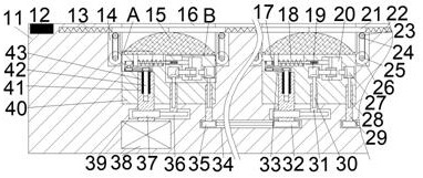
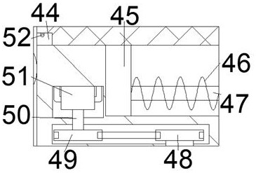
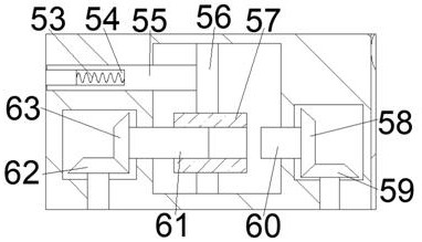
[0014] Combine below Figure 1-3 The present invention is described in detail, wherein, for the convenience of description, the orientations mentioned below are defined as follows: figure 1 The up, down, left, right, front and back directions of the projection relationship itself are the same.

[0015] A safety device for tunnel deceleration according to the present invention includes a box body 11, a moving cavity 16 with an opening facing upward is provided in a transverse array in the box body 11, and a gear cavity 39 is provided on the lower side of the moving cavity 16 The lower side of the gear chamber 39 except the leftmost gear chamber 39 is provided with a synchronous chamber 34, and the left and right sides of the moving chamber 16 are partially communicated and provided with left-right symmetry about the central position of the moving chamber 16 and the opening faces The baffle cavity 13 at the center of the moving cavity 16, the lower part of the baffle cavity 13 ...


PUM


Abstract

The invention discloses a safety device for tunnel deceleration. The device comprises a box body, wherein moving cavities with upward openings are formed in the box body in a transverse array mode, gear cavities are formed in the lower sides of the moving cavities, and synchronization cavities are formed in the lower sides of the gear cavities except the gear cavity on the leftmost side; the leftside part and the right side part of the moving cavity are provided with baffle cavities in a communicating mode, the baffle cavities are in bilateral symmetry about the center position of the movingcavity, openings of the baffle cavities face the center position of the moving cavity, and the lower side parts of the baffle cavities are provided with gear transmission cavities in a communicating mode; the speed of the vehicle is monitored by the sensor so as to control the rise and fall of a speed reducing belt, relative displacement of the automobile to the speed reducing belt is used to control the subsequent speed reducing belt, dust on the outer surface of the deceleration strip can cleaned and absorbed, and the dust is prevented from entering the interior to damage the structure of the device, so precision of a control system is improved, the service life of the control system is prolonged, and vehicles decelerated to a certain numerical value can be prevented from passing throughthe speed reducing belt; therefore, the service life of the speed reducing belt is prolonged.

Description

technical field [0001] The invention relates to the related field of safety devices for tunnels, in particular to a safety device for tunnel deceleration. Background technique [0002] Tunnel is an engineering building buried in the ground, and it is a form of human use of underground space. The speed of vehicles driving in tunnels is often higher than the speed of vehicles on ordinary roads, so it is easy to cause car accidents due to excessive speed, especially just When entering the tunnel, due to the sudden dimming of the light, the driver will not be able to see the road ahead clearly, so it is too late to take measures, which is prone to car accidents; if the traditional speed reduction belt is laid, although it will achieve a certain speed reduction, it will affect the normal driving People's mentality is prone to road rage, which affects the driving psychology of driving after entering the tunnel, and is prone to car accidents, thereby reducing the driver's life safe...

Claims


Application Information

Patent Timeline
Patent Type & Authority Applications(China)
IPC IPC(8): E01F9/529G01P3/00B08B5/04F04B35/04
CPCB08B5/04E01F9/529F04B35/04G01P3/00
Inventor 单于旺
Owner 瑞安斌团电子科技有限公司
Learn More