Manufacturing process of motor stator with locally separated tooth yokes

A technology of motor stator and partial separation, which is applied in the direction of manufacturing motor generators, manufacturing stator/rotor bodies, electrical components, etc., can solve the problems of size error, stator shape deformity, low work efficiency, etc., to facilitate transportation and measurement, avoid Dimensional error, high work efficiency effect

Active Publication Date: 2021-02-12
NINGBO ZHENYU TECH
View PDF4 Cites 7 Cited by
  • Summary
  • Abstract
  • Description
  • Claims
  • Application Information

AI Technical Summary

Problems solved by technology

At present, during the production of this stator assembly, each part of the stator assembly is taken as a unit, and each part is stamped and manufactured separately with a corresponding mold. After the manufacturing is completed, the assembly work is carried out, and two stator cores are assembled into two single pieces, and the two stator cores are wound separately, and finally assembled into a complete motor stator. The assembly process will consume a huge amount of time. In addition, there will be dimensional errors between the spliced ​​surface of the slotted yoke and the stator core of the missing portion of the spliced ​​surface of the slotted yoke. If it is deformed, it will affect the performance of the final motor; if it is heavy, it will cause the phenomenon that the two stator core pieces cannot be combined after winding, resulting in the scrapping of the product
[0003] Therefore, the existing motor stator manufacturing process with partially separated tooth yokes has dimensional errors when assembling components, which will affect the performance of the motor, and there is also a certain risk of scrapping, and the assembly of components takes a long time, resulting in low work efficiency.

Method used


Image

  • Manufacturing process of motor stator with locally separated tooth yokes
  • Manufacturing process of motor stator with locally separated tooth yokes

Examples


Embodiment

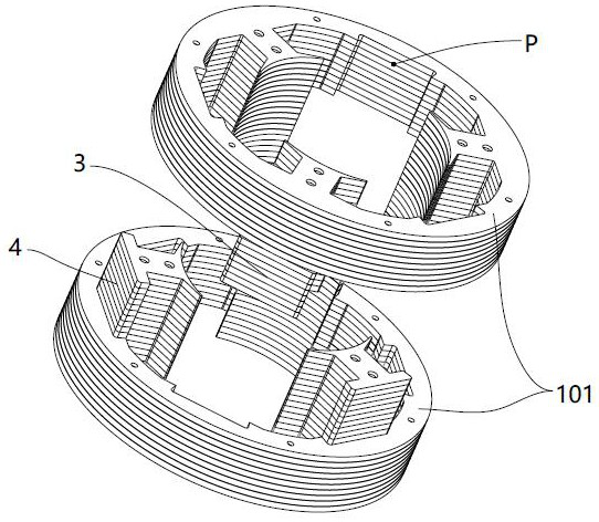
[0035] Embodiment: A motor stator manufacturing process with tooth yoke partially separated, the manufacturing structure is as follows figure 1 The stator core shown, figure 1The stator core includes the base outer ring 101, the even-numbered slot yoke joint surface 4 and the odd-numbered slot yoke joint surface 3, and the manufacturing process specifically includes the following process steps:

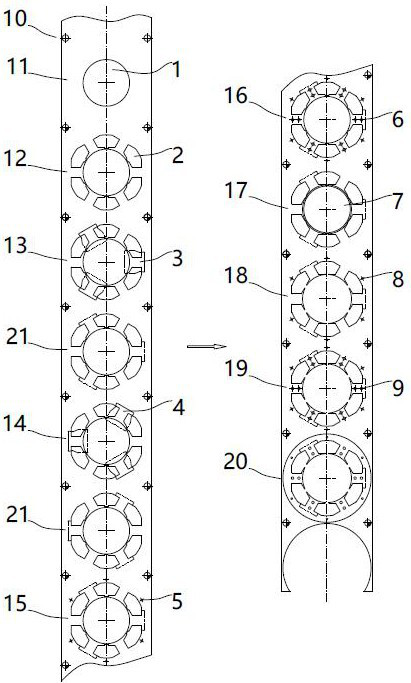
[0036] Step A, feeding: take the strip material and send it to the punching machine, so that the strip material can be continuously fed forward on the punching machine; the punching machine is successively equipped with a punching guide hole station 10 and a punching pre-hole in the forward direction. Station 11, Punching and winding slot hole station 12, Punching odd slot tooth yoke splicing surface station 13, Punching even slot tooth yoke splicing surface station 14, Punching base measurement hole station 15, Punching tooth part measurement hole station 16. Punching inner hole sta...


PUM


Abstract

The invention discloses a manufacturing process of a motor stator with locally separated tooth yokes. The manufacturing process comprises the following process steps: A, feeding; B, punching a windingslotted hole; C, notching the splicing surface of tooth yokes; D, punching a metering hole; E, punching an inner hole; F, punching a buckling point; G, blanking: obtaining a stator iron core; H, performing separation: separating the stator iron cores to obtain two stator iron core single blocks; I, winding: separately winding the two stator iron core single blocks separated in the step H; and J,performing combination: recombining the two stator iron core single blocks wound in the step I along the original separation position to obtain a motor stator finished product. The process has the advantages that the size error is small when all parts are assembled, the rejection rate of products is low, the performance of a motor using the process stator is good, and the working efficiency is high.

Description

technical field [0001] The invention relates to a manufacturing process of a motor stator, in particular to a manufacturing process of a motor stator with tooth yokes partially separated. Background technique [0002] When the stator core is winding, the size of the slot between two adjacent teeth is related to the difficulty and speed of winding. In order to increase the winding speed, a tooth yoke has been developed. Partially separated stator assembly, such as a stator assembly disclosed in Patent Publication No. CN 107546875 A (see attached figure 1 ), which is formed by combining two single stator core blocks, and the spliced ​​surfaces of the slotted yokes of the two single stator cores are arranged crosswise in the circumferential direction, that is, the spliced ​​surfaces of the slotted yokes on each single stator core block are halved, There is enough space between the spliced ​​surfaces of the adjacent tooth yokes of each stator core single block to perform windin...

Claims


Application Information

Patent Timeline
Patent Type & Authority Applications(China)
IPC IPC(8): H02K15/02H02K15/085
CPCH02K15/02H02K15/085
Inventor 邹春华周茂伟朱江华郭银芬
Owner NINGBO ZHENYU TECH
Why Eureka
Try Eureka