Ultra-wide-angle optical imaging system and optical equipment
An optical imaging system and ultra-wide-angle technology, applied in optics, optical components, instruments, etc., can solve the problems of expensive lenses and vacant focal lengths, reduce purple fringing or dispersion, reduce weight, and facilitate fast focusing Effect
- Summary
- Abstract
- Description
- Claims
- Application Information
AI Technical Summary
Problems solved by technology
Method used
Image

Examples
Embodiment 1
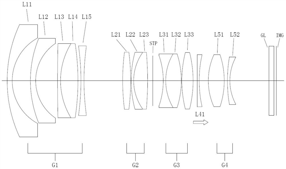
[0085] figure 1 Shown is a schematic structural view of the ultra-wide-angle optical imaging system in Embodiment 1. In Embodiment 1, the first lens group G1 includes a first lens L11 with negative refractive power and a lens with negative refractive power arranged in sequence. The second lens L12, the third lens L13 with negative refractive power, the fourth lens L14 with positive refractive power, and the fifth lens L15 with negative refractive power, the fifth lens L15 is about a wavelength of 587.6nm A low dispersion lens with an Abbe number higher than 70.
[0086] The numerical data of described ultra-wide-angle optical imaging system is shown in Table 1, Table 2 and Table 3:
[0087] Table 1
[0088]
[0089]
[0090] Table 2
[0091]
[0092]
[0093] table 3
[0094]
[0095] Wherein, the surface number represents the surface number of each lens from the object side to the image side;
[0096] In Example 1, the object-side surfaces and image-side s...
Embodiment 2
[0105] Figure 8 Shown is a schematic structural view of the ultra-wide-angle optical imaging system of Embodiment 2. In Embodiment 2, the first lens group G1 includes a first lens L11 with negative refractive power, a lens with negative refractive power, and The second lens L12, the third lens L13 with negative power, and the fourth lens L14 with positive power, the fourth lens group G4 also includes a fifteenth lens L53 with positive power, the tenth The pentalens L53 is disposed on the side of the fourteenth lens L52 away from the object side. Hereinafter, Table 4, Table 5 and Table 6 show various numerical data about the ultra-wide-angle optical imaging system of this embodiment.
[0106] Table 4
[0107]
[0108]
[0109]
[0110] table 5
[0111]
[0112] Table 6
[0113]
[0114] Figure 9-10 Showing the spherical aberration diagram of embodiment 2 at infinity focus and closest focus, Figure 11-14 It shows the curves of curvature of field and distort...
Embodiment 3
[0116] Figure 15 Shown is a schematic structural view of the ultra-wide-angle optical imaging system in Embodiment 3. In Embodiment 3, the first lens group G1 includes a first lens L11 with negative refractive power and a lens with negative refractive power arranged in sequence. The second lens L12, the third lens L13 with negative refractive power, the fourth lens L14 with positive refractive power, and the fifth lens L15 with negative refractive power, the fifth lens L15 is about a wavelength of 587.6nm A low dispersion lens with an Abbe number higher than 70. Hereinafter, Table 7, Table 8 and Table 9 show various numerical data about the ultra-wide-angle optical imaging system of this embodiment.
[0117] Table 7
[0118]
[0119]
[0120] Table 8
[0121]
[0122] Table 9
[0123]
[0124] Figure 16-17 Showing the spherical aberration diagram of embodiment 3 at infinity focus and closest focus, Figure 18-21 It shows the field curvature and distortion c...
PUM
 Abstract
Description
Claims
Application Information
 - Generate Ideas
- Intellectual Property
- Life Sciences
- Materials
- Tech Scout
- Unparalleled Data Quality
- Higher Quality Content
- 60% Fewer Hallucinations
Browse by: Latest US Patents, China's latest patents, Technical Efficacy Thesaurus, Application Domain, Technology Topic, Popular Technical Reports.
© 2025 PatSnap. All rights reserved.Legal|Privacy policy|Modern Slavery Act Transparency Statement|Sitemap|About US| Contact US: help@patsnap.com