
Bidirectional current Hall sensor circuit and current detection method based on circuit

A technology of Hall sensor and bidirectional current, which is applied in the direction of instruments, measuring electronics, measuring devices, etc., and can solve problems such as the inability to realize bidirectional current measurement, the heating of the sampling resistor Ra, and the inability to obtain accurate coil circuits, etc.

Pending Publication Date: 2021-02-12
HANGZHOU ELECTRIC EQUIP MFG
View PDF1 Cites 2 Cited by
  • Summary
  • Abstract
  • Description
  • Claims
  • Application Information

AI Technical Summary

Problems solved by technology

[0004] 1. In the comparison document, the first resistor R1 and the second resistor R2 in the H-bridge drive circuit are connected in series with the coil and then connected to the H-bridge circuit, which causes the circuit in the coil to be shunted by the resistor, which greatly affects the measurement accuracy of the current, and even causes Unable to get exact coil circuit
[0005] 2. In the comparison file, the sampling resistor Ra is connected to the power circuit, and the microcontroller cannot judge the flow direction of the circuit through the voltage of the sampling resistor, that is, the comparison file cannot judge the current direction, and cannot realize two-way current measurement, and the sampling resistor Ra is in this way. Severe fever in the connection relationship
[0006] 3. In the embodiment in the comparison document, the output of the Hall chip is connected to the operational amplifier, and the output of the operational amplifier is directly connected to the H-bridge. In this way, for the triode H-bridge, the triode will not work in the amplified state, because the triode is a current-driven type. However, the output of the op amp is a voltage signal, which cannot drive the H bridge, causing the H bridge to fail to work.
[0007] 4. In the comparison file, the bases of the transistors T1 and T2 of the H bridge are connected together, and the bases of T3 and T4 are connected together, so that the four transistors connected in this way cannot make the current flow through the coil
[0008] To sum up, the technical solution proposed in the comparison document cannot solve the technical problem raised by it, that is, the high-precision bidirectional measurement of current cannot be realized

Method used


Image

  • Bidirectional current Hall sensor circuit and current detection method based on circuit
  • Bidirectional current Hall sensor circuit and current detection method based on circuit
  • Bidirectional current Hall sensor circuit and current detection method based on circuit

Examples


Embodiment 1

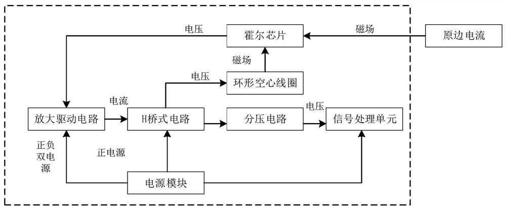
[0040] Such as figure 1 As shown, it is a schematic diagram of the composition and connection relationship of the bidirectional current Hall sensor circuit, including the annular air-core coil 2, the Hall chip 3 located at the gap of the annular air-core coil 2, and the H coupling the Hall chip 3 and the annular air-core coil 2. A bridge circuit, a voltage divider circuit coupled to the H bridge circuit, and a signal processing unit coupled to the voltage divider circuit, an amplifying drive circuit arranged between the Hall chip 3 and the H bridge circuit, and, coupled to the amplifying drive circuits and power modules for H-bridge circuits.

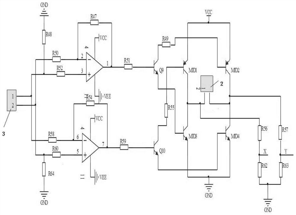
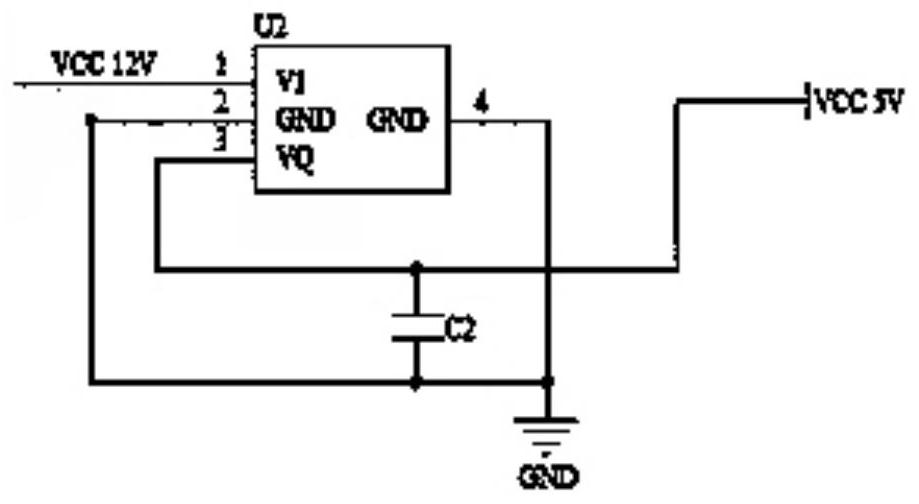
[0041] Combine below Figure 2-Figure 5 The specific embodiment shown further describes in detail the bidirectional current Hall sensor circuit of the present invention,

[0042] Such as figure 2 As shown, the Hall chip 3 induces the induced magnetic field generated by the current 1 to be measured in the annular air-core coil 2, and...


PUM


Abstract

The invention discloses a bidirectional current Hall sensor circuit, which comprises an annular hollow coil, a Hall chip arranged at a notch of the annular hollow coil, an H-bridge circuit coupled with the Hall chip and the annular hollow coil, a voltage division circuit coupled with the H-bridge circuit, a signal processing unit coupled with the voltage division circuit, an amplification drivingcircuit which is arranged between the Hall chip and the H-bridge circuit, and a power supply module which is coupled with the amplification driving circuit and the H-bridge circuit. According to the circuit, the H-bridge circuit is utilized, so that the annular hollow coil generates a bidirectional magnetic field, the output voltage of the voltage division circuit during dynamic magnetic balance is acquired, the current magnitude is calculated, the current direction is judged, the high-current bidirectional flowing current of the energy storage battery is accurately measured, the SOC estimation precision is further improved, and the SOC estimation accuracy is improved. The invention further discloses a current detection method based on the bidirectional current Hall sensor circuit, and high-precision bidirectional measurement of the direct current is achieved.

Description

technical field [0001] The invention relates to the field of current measurement, in particular to a bidirectional current Hall sensor circuit and a current detection method based on the circuit. Background technique [0002] For energy storage power stations and electric vehicle energy storage battery management systems, when accurately estimating the SOC of the remaining battery capacity, it is usually obtained by the current integration method. The SOC estimation accuracy depends on the accuracy of the current measurement sensor. For occasions with energy recovery, such as When braking and stopping to recover energy, there is a current flowing into the battery, and the energy flow is bidirectional. In this way, if the traditional Hall circuit sensor is used, due to the limitation of the detection principle, it is impossible to measure the reverse current. Therefore, if the traditional Hall circuit sensor is used The current sensor measures the current flowing in and out o...

Claims


Application Information

Patent Timeline
Patent Type & Authority Applications(China)
IPC IPC(8): G01R19/25G01R31/3828
CPCG01R19/25G01R31/3828
Inventor 陈建新王根明任新卓潘黄萍张金波
Owner HANGZHOU ELECTRIC EQUIP MFG
Learn More