Eureka AIR delivers breakthrough ideas for toughest innovation challenges, trusted by R&D personnel around the world.

CL thermal insulation system construction method

A construction method and system technology, applied in the direction of thermal insulation, building thermal insulation materials, building components, etc., can solve the problems of complex construction technology, long construction period, high concrete, etc., achieve the effect of safe and efficient construction, simplify construction technology, and meet pouring requirements

Inactive Publication Date: 2021-02-12
CHINA MCC17 GRP
View PDF5 Cites 2 Cited by
  • Summary
  • Abstract
  • Description
  • Claims
  • Application Information

AI Technical Summary

Problems solved by technology

[0003] However, the construction technology of CL thermal insulation system has high requirements on the self-compacting performance of concrete and concrete pouring technology, especially the extremely high requirements on the flatness and verticality of the facade wall, the construction process is complex, the construction period is long, and the cost is high

Method used


Image

  • CL thermal insulation system construction method
  • CL thermal insulation system construction method
  • CL thermal insulation system construction method

Examples


Embodiment Construction

[0032] The following will clearly and completely describe the technical solutions in the embodiments of the present invention with reference to the accompanying drawings in the embodiments of the present invention. Obviously, the described embodiments are only some, not all, embodiments of the present invention. Based on the embodiments of the present invention, all other embodiments obtained by persons of ordinary skill in the art without making creative efforts belong to the protection scope of the present invention.

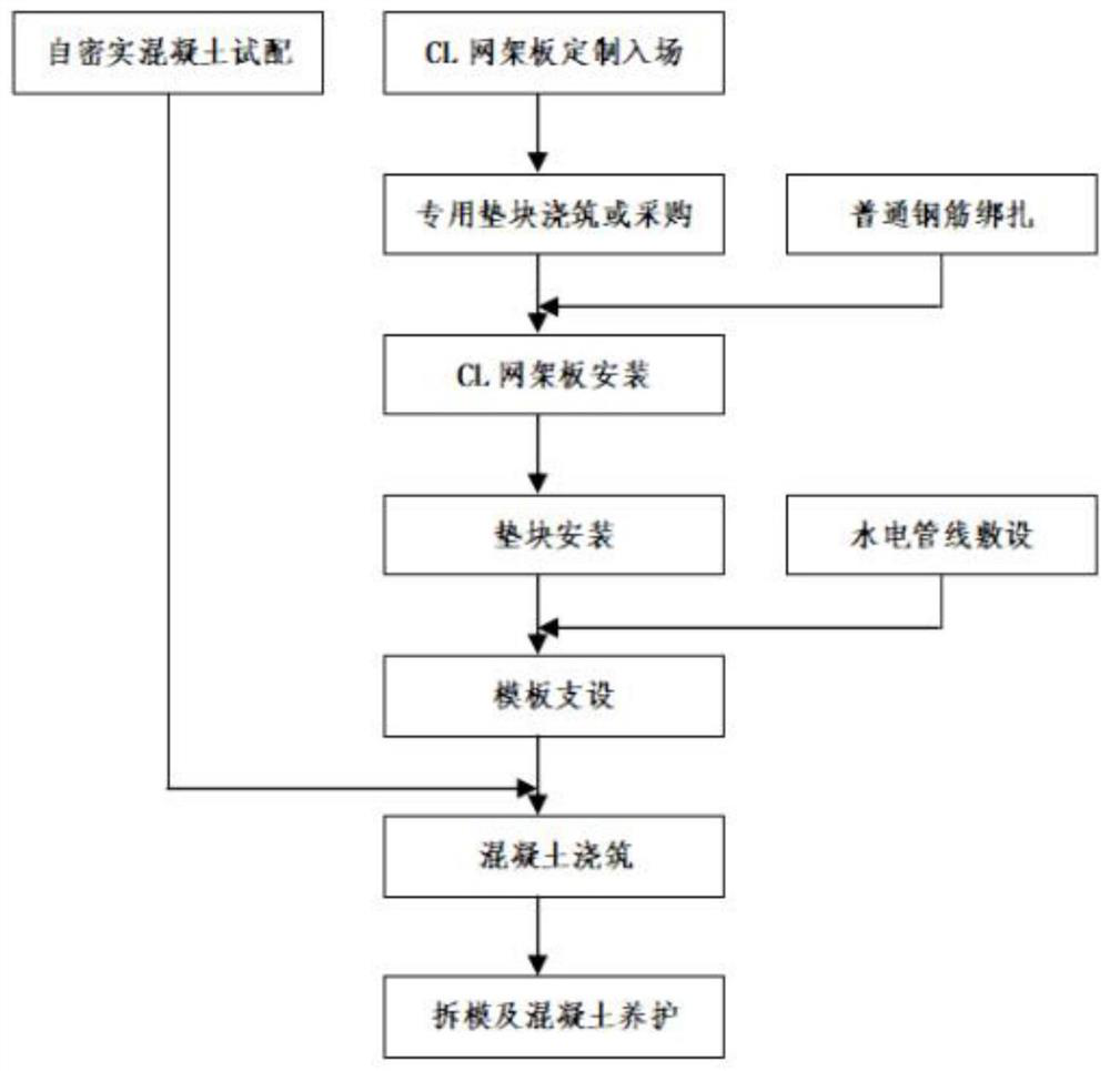
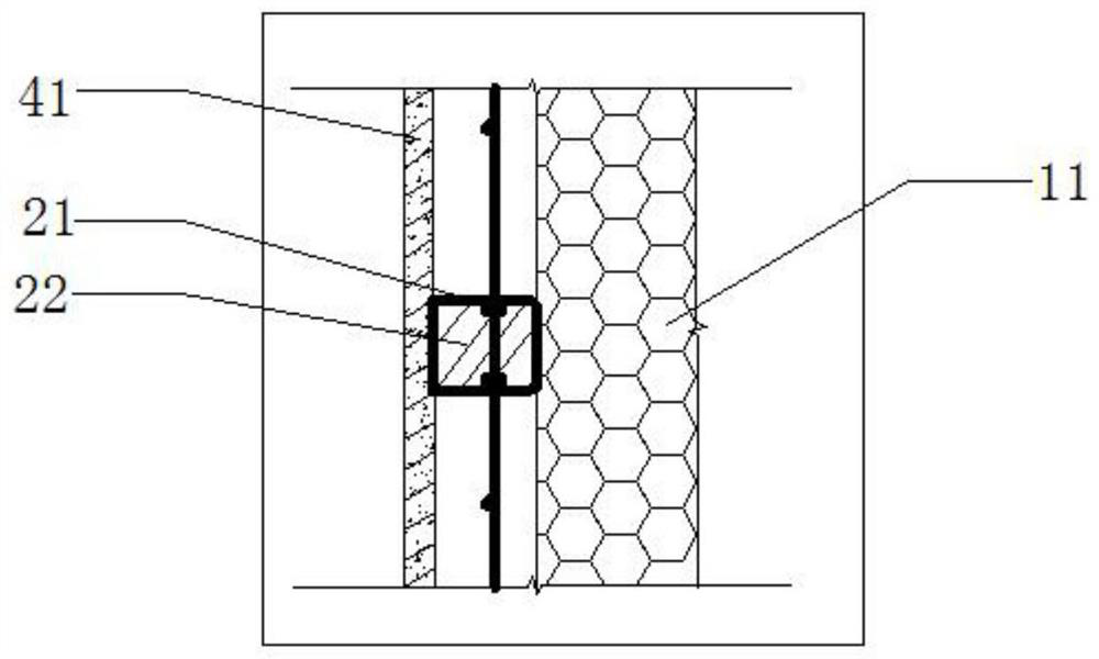
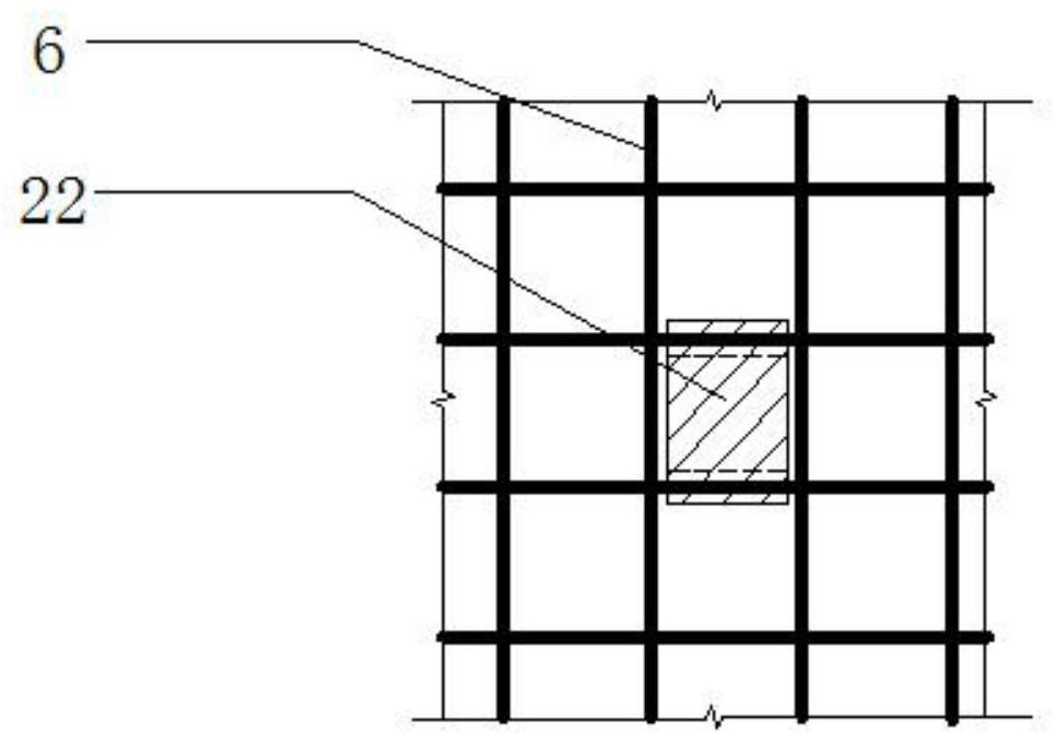
[0033] see figure 1 , in the embodiment of the present invention: provide a kind of construction method of CL thermal insulation system, CL thermal insulation system is also called CL composite thermal insulation steel bar welded grid concrete shear wall, is made of CL grid plate 6 (a kind of two-layer steel bar welded grid The grid frame welded by three-dimensional obliquely inserted steel bars with insulation boards 11 in the center) is formed after pouring ...


PUM


Abstract

The invention discloses a CL thermal insulation system construction method, and belongs to the technical field of building construction. The method includes the steps that the customizing, decomposingand numbering of CL net rack plates is conducted; additional steel bars are mounted on the CL net rack plate; the CL net rack plate is installed, and the CL net rack plate is bound and fixed with fixing steel bars; a plurality of special cushion blocks are installed at the two sides of the CL net rack plate, and water and electricity pipelines are laid; a formwork used for concrete pouring is installed on the CL net rack plate, through-wall bolts are arranged on the formwork, and self-compacting concrete is matched in a trial mode; and self-compacting concrete is poured, the formwork is removed, and the concrete is maintained. According to the CL thermal insulation system construction method, the structure erecting work of a CL heat preservation system can be simply and rapidly completed,the construction process is simplified, cost is reduced, and stability and firmness are achieved; and the in-mold temperature and pouring points are controlled, the special cushion blocks are arranged at certain intervals, and the concrete pouring height difference between the two sides of the heat preservation plate is controlled, so that the situation that the CL net rack plate does not generate lateral displacement is guaranteed, the pouring requirement and pouring quality of the concrete are met, and the construction is safe and efficient.

Description

technical field [0001] The invention relates to the technical field of building construction, in particular to a construction method of a CL thermal insulation system. Background technique [0002] The CL thermal insulation system is also called the CL composite thermal insulation reinforced welded grid concrete shear wall. Frame) is a wall that is both force-bearing and heat-insulating after pouring concrete on both sides. The CL thermal insulation system is 2-3 earthquake-resistant higher than the brick-concrete structure, which can reach the national energy-saving standard of 75%, and the thermal insulation layer has the same service life as the main body of the building, which fundamentally overcomes the lack of durability of other external wall insulation and external wall internal insulation. It can also reduce the thickness of the wall, expand the usable area by 5%-8%, and realize the industrialization of construction and housing. [0003] However, the construction ...

Claims


Application Information

Patent Timeline
Patent Type & Authority Applications(China)
IPC IPC(8): E04B1/80E04B1/66E04G21/14E04G21/12E04G21/02E04G21/24
CPCE04B1/66E04B1/80E04G21/02E04G21/12E04G21/122E04G21/14E04G21/246
Inventor 赵幸发李征
Owner CHINA MCC17 GRP
Why Eureka
Eureka Blog
Learn More