A vertical wall sliding installation support device and its construction method

A technology for sliding installation and support device, applied in the field of civil engineering, can solve the problems of complex situation, complex road structure, increase the operating cost of wheeled cranes, etc., and achieve the effects of cost saving, convenient installation and assembly operations, and simple structure

Active Publication Date: 2022-04-15
HEFEI WISDOM DRAGON MACHINERY DESIGN CO LTD
View PDF8 Cites 0 Cited by
  • Summary
  • Abstract
  • Description
  • Claims
  • Application Information

AI Technical Summary

Problems solved by technology

However, in the actual operation process, the author found that there are many disadvantages in this method, and these disadvantages are concentrated in: because the steel frame of the vertical wall inevitably needs to be hoisted during the installation process, the current construction method is to put the frame of the vertical wall The assembly is carried out at a position far away from the cave body. After the assembly is completed, use multiple wheeled cranes to transport it to the vicinity of the cave body, and then use crawler cranes to carry out the unloading operation. Due to the small lifting capacity of the wheeled cranes, multiple wheeled cranes are required. Complete the transshipment operation of the steel frame of the vertical wall. Because the crawler crane has a large load capacity and there are many supporting points for lifting the load, the crawler crane is used to carry out the unloading operation after aligning the hole. Because the steel frame of the vertical wall is assembled During the process, it is necessary to stay away from the hole to a safe area and location, and to facilitate the transportation of incoming materials and installation operations. Therefore, the assembly of the vertical wall frame is far away from the hole, which has caused certain defects. If only crawler cranes are used, Because the bottom of the crawler crane is generally required to be stable during construction, if the assembly position of the vertical wall frame exceeds the travel distance of the crawler crane, it is necessary to use multiple wheeled cranes to assist in the transportation of the vertical wall reinforcement frame to the crawler crane. However, in the specific construction process, due to site constraints and construction safety requirements, the assembly of the vertical wall frame must be far away from the design of the opening, which increases the operating cost of the wheeled crane and must be used The combination of wheeled cranes and crawler cranes can carry out the operation of cutting the steel frame of the vertical wall into the hole. Generally, the site conditions of the construction site are complicated, and the road surface structure is complex. It is very difficult to use wheeled cranes, and at least two wheeled cranes are required. The steel frame of the vertical wall can only be transported to the vicinity of the cave with the cooperation of the crane. The construction is very difficult and the efficiency is low, which makes the construction more difficult and affects the overall construction progress of the vertical wall.

Method used


Image

  • A vertical wall sliding installation support device and its construction method
  • A vertical wall sliding installation support device and its construction method
  • A vertical wall sliding installation support device and its construction method

Examples


Embodiment Construction

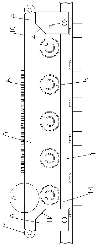
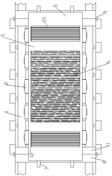
[0025] Such as figure 1 , 2 , 3, 4, 5, 6, 7, and 8, a vertical wall sliding installation support device includes a translation trolley 3 installed on the translation track 1 through track wheels 2, and the bottoms at both ends of the translation trolley 3 All are provided with inclined retaining grooves 4, and the outer ends of the translation trolley 3 outside the inclined retaining grooves 11 are fixedly equipped with reinforced support seats 5, and the center position of the top surface of each reinforced support seat 5 is provided with a displacement rotation groove 12, and the displacement rotation The groove 12 is a groove-like structure with a semicircular cross section. A number of rollers 10 are movably installed on the inner wall of the displacement rotation groove 12 in the length direction. Raise the anti-skid support layer 6, a rotating support device is movably installed on at least one side of the raised anti-skid support layer 6, and a bottom limit support blo...


PUM


Abstract

The invention relates to a support device for sliding installation of a vertical wall and a construction method thereof. Inclined retaining grooves are arranged at the bottoms of both ends of the translation trolley, and a reinforced support seat is fixedly installed on the outer end of the translation trolley outside the inclined retaining groove. The center of the top surface of the supporting seat is provided with a displacement rotation groove. The displacement rotation groove is a groove structure with a semicircular cross section. Several rollers are movably installed on the inner wall of the displacement rotation groove in the length direction. The center position of the top of the translation trolley is fixedly installed with an elevated anti-slip support layer, and a rotating support device is installed on at least one side of the raised anti-slip support layer, and a bottom is clamped on at least one side of the translation trolley. The limit support block, the top of the bottom limit support block is provided with an inclined support groove that matches the inclined retaining groove; the mobile platform is used to transfer the steel frame of the vertical wall to the opening of the vertical wall, realizing the transfer without the need for a wheeled crane. The cost is greatly saved, and the installation and construction work of each vertical wall can be completed by using a crawler crane, which can save a lot of money.

Description

technical field [0001] The invention relates to the field of civil engineering, in particular to a vertical wall sliding installation support device and a construction method thereof. Background technique [0002] The vertical wall is the most common wall in civil engineering. The vertical wall in civil engineering generally refers to the facade wall that needs to be embedded in the tunnel or underground structure. These walls are mostly prefabricated with steel structures and require length and width. And the thickness of the steel frame wall, and then dig out the foundation hole on the ground that matches the length, width and thickness of the vertical wall, and then slowly drop the prefabricated vertical wall into the hole from bottom to top, and finally in the vertical Concrete is poured into the steel frame of the wall and finally made into vertical walls that need to be pre-buried in the ground. These vertical walls provide internal support for later tunnel constructio...

Claims


Application Information

Patent Timeline
Patent Type & Authority Patents(China)
IPC IPC(8): E02D29/045B66C13/08B66C13/00
CPCE02D29/045B66C13/08B66C13/00
Inventor 赵晋王仪王松威郭平功马政伟武海荣尤培波屈讼昭
Owner HEFEI WISDOM DRAGON MACHINERY DESIGN CO LTD
Why Eureka
Try Eureka