Screw-in type water flow comprehensive indicator for self-generating electricity by utilizing vortex-induced vibration

A vortex-induced vibration and indicator technology, which is used in current collectors, generators/motors, instruments, etc., can solve the problems of time-consuming, labor-intensive, and artificial observation, and achieve the effects of accurate measurement, small impact, and simple overall structure.

Pending Publication Date: 2021-02-09
九江中船消防设备有限公司
View PDF0 Cites 0 Cited by
  • Summary
  • Abstract
  • Description
  • Claims
  • Application Information

AI Technical Summary

Problems solved by technology

Traditional water flow indicators are either mechanical feedback, unable to achieve data feedback and collection, and require human observation; or they need long-distance power supply to display their flow status and feed back data through cables, which means how long the pipeline is As far as the length of the cable is concerned, an additional base station may be required for data collection; Structurally speaking, most water flow indicators currently use saddle-shaped or clip-on type, and the installation of this type of water flow indicator needs to be done in the early stage of the pipeline , it will be time-consuming and labor-intensive if the dark transfer is carried out on the existing pipeline

Method used


Image

  • Screw-in type water flow comprehensive indicator for self-generating electricity by utilizing vortex-induced vibration
  • Screw-in type water flow comprehensive indicator for self-generating electricity by utilizing vortex-induced vibration
  • Screw-in type water flow comprehensive indicator for self-generating electricity by utilizing vortex-induced vibration

Examples


Embodiment Construction

[0035] In describing the present invention, it should be understood that the terms "center", "longitudinal", "transverse", "upper", "lower", "front", "rear", "left", "right", " The orientations or positional relationships indicated by "vertical", "horizontal", "top", "bottom", "inner" and "outer" are based on the orientations or positional relationships shown in the drawings, and are only for the convenience of describing the present invention and Simplified descriptions, rather than indicating or implying that the device or element referred to must have a particular orientation, be constructed and operate in a particular orientation, and thus should not be construed as limiting the invention. In the description of the present invention, unless otherwise specified, "plurality" means two or more.

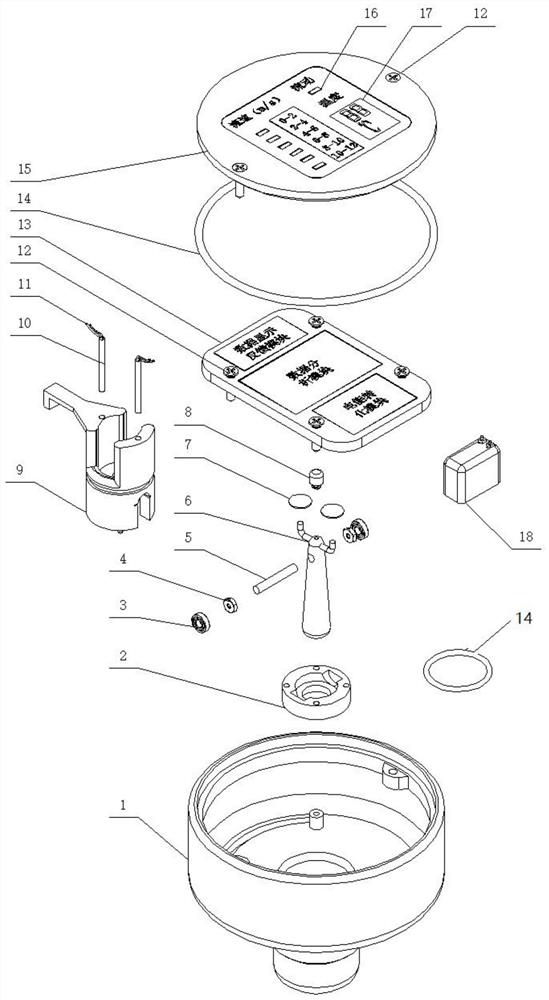
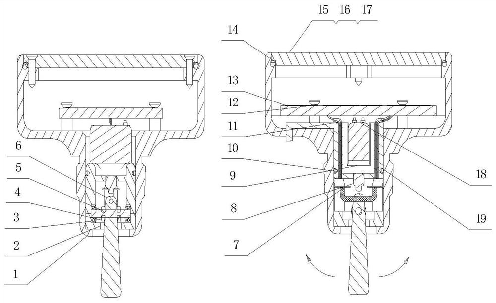
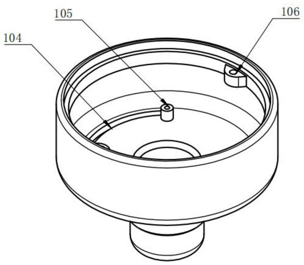
[0036] The invention will be described in detail below in conjunction with the accompanying drawings and embodiments.

[0037] Such as Figure 1-11As shown, the present invention p...


PUM


Abstract

The invention discloses a screw-in type water flow comprehensive indicator for self-generating electricity by utilizing vortex-induced vibration, which is characterized in that the indicator comprisesan indicator shell, a vibration rod mounting ring, a vibration device, a vibration rod adjuster, a battery pack, a circuit board and a display panel which are sequentially mounted from bottom to top;the indicator shell comprises a sealing pipe thread used for being connected with a pipeline, a vibration rod through hole used for allowing the vibration device to penetrate through the indicator shell and stretch into the pipeline, and a mounting inner cavity used for containing the vibration rod mounting ring and the vibration rod adjuster; and an adjusting groove matched with the vibration rod adjuster to enable an adjusting knob to extend out of the device is formed in the indicator shell, a mounting groove used for fixing the vibration device is formed in the vibration rod mounting ring, and the vibration device is connected with the vibration rod adjuster. According to the invention, the vibration device can generate different amplitudes and frequencies due to vortex-induced vibration, under the condition that the damping, mass, rigidity, boundaries and other factors of the structure are fixed, the amplitude, the frequency and the flow velocity have an invariable rule, and theflow velocity can be accurately measured through the rule.

Description

technical field [0001] The invention relates to the technical field of monitoring water flow, in particular to a screw-in integrated water flow indicator which uses vortex-induced vibration to generate electricity by itself. Background technique [0002] With the exploration of the earth and the expansion of cities, infrastructure is spread all over the world, and urban agglomerations are becoming larger and more complex. Submarine oil pipelines, tap water supply in remote mountain villages, urban underground fire water pipelines, and intricate transportation pipelines in modern factories all need to be monitored and monitored, and pipeline monitoring in remote and hard-to-reach areas has always been a problem . Either artificially observe, or use cables for power supply and data feedback, whether it is the former or the latter, monitoring and monitoring the flow status of pipelines is troublesome, time-consuming and labor-intensive. In contrast to cities, fire protection ...

Claims


Application Information

Patent Timeline
Patent Type & Authority Applications(China)
IPC IPC(8): G01P5/08H02J7/32H02N2/18
CPCG01P5/083H02J7/32H02N2/185H02N2/186
Inventor 乐智斌崔宇光曾银平何涛张玉佼
Owner 九江中船消防设备有限公司
Why Eureka
Try Eureka