
Three-dimensional dilatometer and working method thereof

A dilatometer, three-dimensional technology, applied in instruments, scientific instruments, measuring devices, etc., can solve problems such as inability to effectively monitor the three-dimensional expansion characteristics of soil samples, improve detection efficiency and accuracy, ensure measurement accuracy and effect, and improve accuracy. degree of effect

Pending Publication Date: 2021-02-09
NANJING INST OF TECH
View PDF0 Cites 2 Cited by
  • Summary
  • Abstract
  • Description
  • Claims
  • Application Information

AI Technical Summary

Problems solved by technology

[0003] The technical problem to be solved by the present invention is to provide a three-dimensional dilatometer capable of monitoring the three-dimensional deformation and expansion force in the process of soil sample expansion in real time, which solves the problem that the existing dilatometer cannot effectively monitor the three-dimensional expansion characteristics of the soil sample; Further, the present invention provides a three-dimensional dilatometer that can be used to verify the deformation of soil samples and ensure the measurement accuracy and effect of the dilatometer

Method used


Image

  • Three-dimensional dilatometer and working method thereof

Examples


specific Embodiment 1

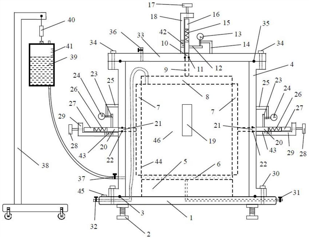
[0025] Such as figure 1 As shown, the present invention provides a three-dimensional dilatometer, which includes a base 1 on which a balancing water drop 45 is arranged, and a base adjusting bolt 2 is fixed on the lower part of the base 1 . The base 1 is provided with a pressure chamber side cylinder 4, and the pressure chamber side cylinder 4 has a square structure. The pressure chamber side cylinder 4 is fixed on the base 1 by base bolts 30 , and the bottom of the pressure chamber side cylinder 4 and the top of the base 1 are provided with a base sealing ring 3 . The pressure chamber side cylinder 4 is provided with a top cover 33 , the pressure chamber side cylinder 4 and the top cover 33 are fixed by the top cover bolts 34 , and the top cover sealing ring 35 is provided at the bottom of the top cover 33 and the top of the pressure chamber side cylinder 4 .

[0026] A top plate 8 and a bottom plate 5 are arranged in the upper and lower directions in the side cylinder 4 of ...

specific Embodiment 2

[0032] This embodiment is the same as the specific embodiment 1, the only difference is that no rubber film is provided on the side of the soil sample, and the top plate and the side plate are directly connected with the soil sample.

[0033] The working process of the present invention is: when in use, open the side cylinder valve or the top cover valve, open the bottom plate valve and the top plate valve. After preparation, record the initial readings of the top dial gauge, top load cell, side dial gauge, side load cell, top bracket scale, and side bracket scale, respectively. Saturate the soil sample with water from the bottom plate valve, measure the expansion deformation and expansion force of the roof and side plates at different water intake times, the top expansion deformation is calculated by the top dial gauge, and the top expansion deformation is verified by the top bracket scale; the top expansion The force is calculated by the top load sensor; the side expansion d...

specific Embodiment 3

[0035] This embodiment is the same as the specific embodiment 2, and the difference is only in the working process.

[0036] The working process of the present invention is: when in use, close the side cylinder valve and the top plate valve, open the bottom plate valve and the top cover valve. After preparation, record the initial readings of the top dial gauge, top load cell, side dial gauge, side load cell, top bracket scale, and side bracket scale, respectively. Saturate the soil sample with water from the bottom plate valve to ensure that the water level in the pressure chamber of the dilatometer is at least a certain depth higher than the top surface of the soil sample. Measure the expansion deformation and expansion force of the top plate and side plates at different water intake times. The expansion deformation of the top is determined by the top Calculated by the dial gauge, the top expansion deformation is verified through the top bracket scale; the top expansion forc...


PUM


Abstract

The invention discloses a three-dimensional dilatometer. The three-dimensional dilatometer comprises a base; a pressure chamber side cylinder is arranged on the base; a top cover is arranged on the pressure chamber side cylinder; a top plate and a bottom plate are arranged in the pressure chamber side cylinder in the vertical direction; four side plates are transversely and movably arranged between the top plate and the bottom plate; rubber membranes are arranged on the inner sides of the side plates; the upper ends of the rubber membranes are fixed to the side face of the top plate; a permeable stone is arranged on the bottom plate; a soil sample located inside the rubber membrane is placed on the permeable stone; four side face measuring units are arranged on the side faces of the pressure chamber side cylinder; each side face measuring unit is composed of a transverse displacement and load measuring device element; a vertical displacement and load measuring device element is arranged on the top cover. the transverse displacement and load measuring device elements are connected with the outer sides of the side plates; the vertical displacement and load measuring device element isconnected with the top plate. The invention further discloses a working method of the three-dimensional dilatometer. According to the three-dimensional dilatometer and the working method thereof, three-dimensional deformation and expansion force in a soil sample expansion process can be monitored in real time, meanwhile, deformation of the soil sample can be verified, and the measurement precision and effect of the dilatometer are guaranteed.

Description

technical field [0001] The invention relates to a three-dimensional dilatometer and a working method thereof, belonging to the technical field of soil detection. Background technique [0002] Existing dilatometers used to measure soil samples are difficult to measure the expansion force and expansion deformation in three directions of soil samples. If more cylindrical sample dilatometers are used, they can only measure the vertical deformation of soil samples, and cannot directly Measure the lateral deformation. The lateral deformation is obtained by converting the volume of the soil sample and the vertical deformation. At the same time, the expansion force generated by the lateral deformation of the soil is often difficult to measure with the existing dilatometer. There is also a two-dimensional dilatometer, which can only measure the deformation or expansion force in two directions, and the deformation in the other direction cannot be directly measured, and it needs to be ...

Claims


Application Information

Patent Timeline
IPC IPC(8): G01N33/24G01N3/12G01N3/06
CPCG01N3/062G01N3/12G01N33/24G01N2203/0048G01N2203/0605G01N2203/0682
Inventor 姜景山张超韦有信金华赵延喜
Owner NANJING INST OF TECH
Learn More