
Automatic pattern turning machine

A technology of automatic cars and flower machines, which is applied in decorative art, clothing, jewelry, etc., can solve the problems of low production efficiency, time-consuming and labor-intensive, and achieve the effect of improving production efficiency

Inactive Publication Date: 2021-02-09
福大利珠宝(深圳)有限公司
View PDF5 Cites 1 Cited by
  • Summary
  • Abstract
  • Description
  • Claims
  • Application Information

AI Technical Summary

Problems solved by technology

Regarding the related technology, the inventor believes that there are the following defects: the existing embossing machine needs to manually send these jewelry sheets one by one to the embossing machine for embossing, which is time-consuming and laborious, and the production efficiency is low

Method used


Image

  • Automatic pattern turning machine
  • Automatic pattern turning machine
  • Automatic pattern turning machine

Examples


Embodiment 1

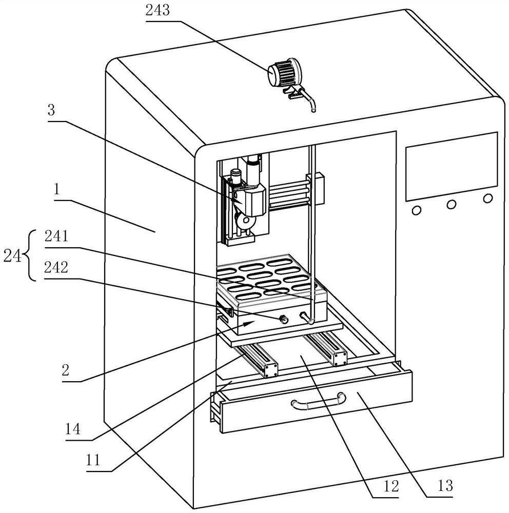
[0039] The embodiment of the present application discloses an automatic car embroidery machine, referring to figure 1 , including a frame 1, a tablet positioning device 2 arranged on the frame 1, and an embossing device 3 arranged on the frame 1 to perform embossing on the tablet, and the embossing device 3 is located above the tablet positioning device 2.

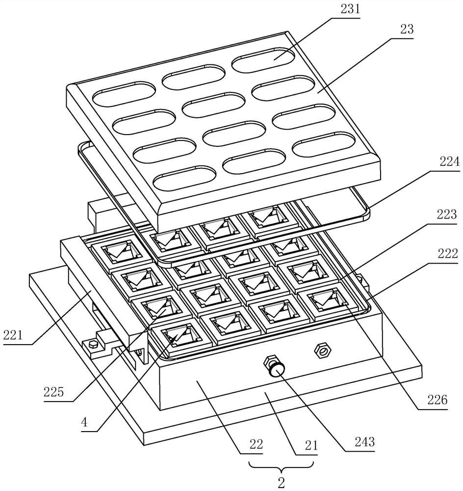
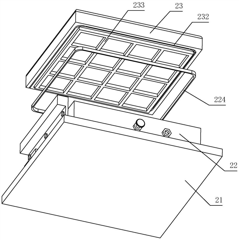
[0040] refer to figure 1 , figure 2 The frame 1 is provided with a support frame 11 and a chip box 13 whose upper part is open and located below the support frame 11. The chip box 13 is slidably connected to the frame 1 in the longitudinal direction, and the support frame 11 is opened to communicate with the chip box. The chip opening 12 of the box 13. The tablet positioning device 2 includes a mounting plate 21 longitudinally slidably connected to the support frame 11, an adsorption template 22 arranged in a cavity and installed on the installation plate 21, and a positioning template placed on the adsorption template ...

Embodiment 2

[0052] The difference with embodiment 1 is: refer to Figure 10 , Figure 11 The lower end surface of the positioning template 23 protrudes and is provided with a plug-in piece 6 inserted in the adsorption hole 225. The plug-in piece 6 includes a connecting column 61 protruding vertically and fixedly connected to the lower end surface of the positioning template 23 and fixedly connected to the The guide post 62 at the lower end of the connecting post 61, the cross section of the connecting post 61 and the guide post 62 is square, the guide post 62 is tapered, the upper end of the guide post 62 is a large end and the lower end of the guide post 62 is a small end. The connecting column 61 is provided with a third sealing groove 611 around the circumference, and the third sealing groove 611 is embedded with a second sealing strip 612. When the connecting column 61 is inserted into the adsorption hole 225, the second sealing strip 612 abuts against the stopper. end face of sheet ...


PUM


Abstract

The invention relates to an automatic pattern turning machine. The automatic pattern turning machine comprises a machine frame, a material sheet positioning device arranged on the machine frame and apattern turning device arranged on the machine frame and used for carrying out pattern turning machining on a material sheet, wherein the pattern turning device is located above the material sheet positioning device; the material sheet positioning device comprises a mounting plate arranged on the machine frame, a suction mold plate arranged in a cavity mode and mounted on the mounting plate, a positioning mold plate placed on the suction mold plate and used for the material sheet to be place, and an air suction assembly used for sucking air in a cavity of the suction mold plate to suck the positioning mold plate on the suction mold plate, the positioning mold plate is provided with a plurality of suction holes which communicate with the suction mold plate cavity to suck the positioning mold plate, the upper end face of the positioning mold plate is provided with a plurality of fixing grooves, and a material sheet is fixed in the fixing grooves in a bonding mode. The automatic pattern turning machine has the effect of improving the jewelry machining production efficiency.

Description

technical field [0001] The present application relates to the technical field of jewelry processing, in particular to an automatic turning machine. Background technique [0002] There are a lot of flake-shaped precious metal jewelry in the jewelry, and these jewelry flakes are all provided with patterns, and these patterns all need car embossing machines for car embossing processing. Regarding the related technology, the inventor believes that there are the following defects: the existing embossing machine needs to manually send these jewelry sheets one by one to the embossing machine for embossing, which is time-consuming and laborious, and the production efficiency is low. Contents of the invention [0003] In order to improve the production efficiency of jewelry processing, the application provides an automatic turning machine. [0004] A kind of automatic car embroidery machine provided by the application adopts the following technical scheme: [0005] An automatic c...

Claims


Application Information

Patent Timeline
Patent Type & Authority Applications(China)
IPC IPC(8): B44C3/00A44C27/00
CPCA44C27/00B44C3/00
Inventor 聂玉龙褚泉泉黄俊昶张城铭周荣辉
Owner 福大利珠宝(深圳)有限公司
Learn More