
A kind of liquid metal cooling directional solidification casting and measuring method of shell temperature

A liquid metal cooling and directional solidification technology, applied in thermometers, measuring heat, measuring devices, etc., can solve problems such as shell cracks, increase the impact of temperature changes, and short-circuit thermocouples, so as to achieve the effect of not being prone to cracks and reducing the impact

Active Publication Date: 2022-05-06
SHENYANG RES INST OF FOUNDRY
View PDF11 Cites 0 Cited by
  • Summary
  • Abstract
  • Description
  • Claims
  • Application Information

AI Technical Summary

Problems solved by technology

[0003] Many literatures have published the cooling curve of castings in the process of liquid metal cooling and directional solidification, but few literatures describe the temperature measurement method in detail
Patent Publication No. CN102507033A discloses a method for measuring the temperature of castings during liquid metal cooling and directional solidification. This method is for the position where the thermocouple is located in the holding furnace: or the thermocouple is buried in the casting shell, and the temperature measurement test is added to the casting solidification process. Due to the influence of temperature changes, and the mold shell cracks after the casting is partially solidified, the thermocouple is easily short-circuited; or it is protected by an integral ceramic insulating tube. During the temperature measurement experiment, due to the large difference in thermal expansion coefficient between the insulating tube and the shell, the thermocouple seal is easy to Cracks occur, and liquid metal for cooling enters the protection tube and short-circuits the thermocouple

Method used


Image

  • A kind of liquid metal cooling directional solidification casting and measuring method of shell temperature
  • A kind of liquid metal cooling directional solidification casting and measuring method of shell temperature

Examples


Embodiment Construction

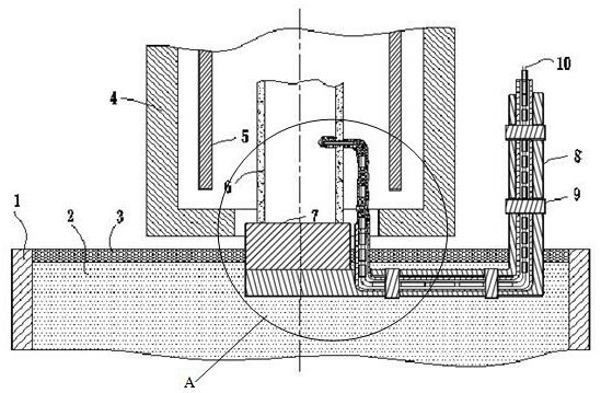
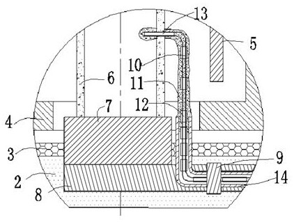
[0025] Referring to the accompanying drawings, a liquid metal cooling directional solidification casting and mold shell, including liquid metal container for cooling (1), liquid metal for cooling (2), floating heat insulation baffle (3), holding furnace (4), graphite Heating body (5), ceramic shell (6), chilling plate (7), bracket (8), pipe collar (9), thermocouple (10), ceramic slurry and refractory aggregate protective layer (11) , the first ceramic insulating section (12), the second ceramic insulating section (13), the molded ceramic protection tube (14), the cooling liquid metal (2) is set in the cooling liquid metal container (1), and the cooling liquid metal A floating heat insulation baffle (3) is arranged on the metal container (1) and the cooling liquid metal (2), and a chilling plate (7) and a bracket (8) are arranged in the cooling liquid metal container (1). A ceramic shell (6) is set on the cold plate (7), a holding furnace (4) is set on the outer circumference o...


PUM

PropertyMeasurementUnit
thicknessaaaaaaaaaa
thicknessaaaaaaaaaa
diameteraaaaaaaaaa

Abstract

A method for measuring the temperature of liquid metal cooling directional solidification castings and mold shells. According to the structure and size design of ceramic mold shells, chilling plates, and brackets, molded ceramic protective tubes are manufactured. After the ceramic mold shells are installed and fastened, the thermocouples are put on The first ceramic insulating section and the second ceramic insulating section are inserted into the molded ceramic protection tube, and the molded ceramic protection tube is fixed on the bracket with a pipe collar, and the ceramic slurry and refractory aggregate protective layer are used to seal the molded ceramic protection tube and thermocouple Dip the measuring end of the thermocouple with a layer of ceramic slurry and insert it into the reserved hole of the mold shell, and fix it with ceramic slurry and refractory aggregate protective layer. The part of the thermocouple located in the holding furnace is made of ceramic slurry and refractory aggregate. Aggregate cover seal. The invention eliminates the influence of cracks in the ceramic mold shell on temperature measurement, does not generate large stress in the thermocouple protective layer, and is not prone to cracks, and is applied in the technical field of casting single crystal / directional superalloy blades prepared by liquid metal cooling method.

Description

technical field [0001] The invention relates to a method for measuring the temperature of liquid metal cooling and directional solidification castings and mold shells in the technical field of single crystal / directional superalloy blade casting prepared by liquid metal cooling method, and in particular relates to castings and mold shells in the process of liquid metal cooling and directional solidification temperature measurement. Background technique [0002] At present, with the development of gas turbines, the demand for large-size oriented and single-crystal castings is increasing. Therefore, the liquid metal cooling and directional solidification process used in the production of large-size oriented and single-crystal castings has also attracted more and more attention. The heat exchange is complicated during the cooling and directional process of superalloy liquid metal. Analyzing this process with the help of numerical simulation software has become the method for the...

Claims


Application Information

Patent Timeline
Patent Type & Authority Patents(China)
IPC IPC(8): B22D2/00B22D27/04G01K7/02
CPCB22D2/00B22D27/045G01K7/02
Inventor 税国彦郭新力刘可孙逊金磊
Owner SHENYANG RES INST OF FOUNDRY
Learn More